3D printable flying wing generator
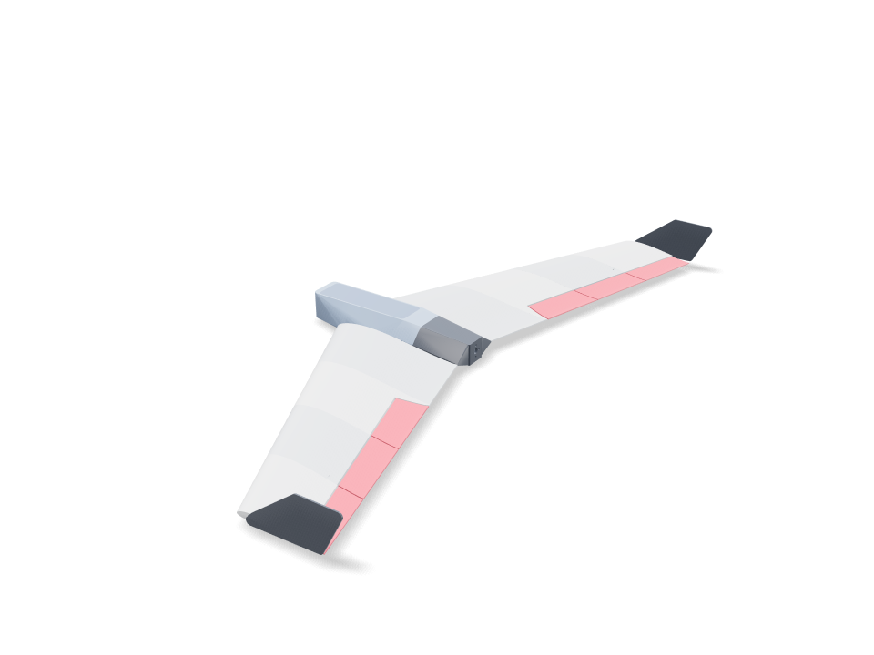
Built around the parts everyone already has: a 2212 motor as a pusher, a 30 A ESC, a 4S 1500 mAh LiPo (or 3S 2200), two MG90S servos and a small receiver. The wing is a reflexed MH45-class airfoil lofted with sweep, taper and washout. Tip-plate winglets give it yaw stability. The LW-PLA panels are hollow skins braced by a crossed lattice modelled in the CAD, over a carbon spar and a joiner. Every component is placed in the model: the battery in a pod under a hatch that snaps on, each servo screwed into a PETG frame that bolts into a pocket under the wing, with a wire channel to the receiver, the motor on a tail cone that slides off so a screwdriver can reach its screws, and the ESC in a recess under the wing where the air cools it. Each part is weighed from its real volume and material, together with each component, and the check confirms the battery can slide to the balance point. Each part is printed in the material its job needs: LW-PLA where weight matters, PETG for the tail cone that carries the warm motor and ESC, the snap hatch and the servo frames, PLA for the thin winglets, and TPU for the flexible hinges. Press Use it to see the elevons move for pitch and roll, and the assembly plays in the real build order.
Ask for the sizes you want to tweak, e.g. “make the width adjustable”.
Specs at the default size
Measured from the actual build on a Bambu Lab A1 in PLA. Every number updates live when you drag a slider above.
- Overall size
- 436 × 994 × 86 mm
- Parts
- 36
- Filament
- 427 g
- Print time
- 21 h 50 min
- Build plates
- 3
- Supports
- Some parts
Engineering checks
- Modeled lattice in panel 1 R13342.5 mm3 of internal CAD material; not slicer infill or a strength qualification
- Modeled lattice in panel 2 R11146.3 mm3 of internal CAD material; not slicer infill or a strength qualification
- Modeled lattice in elevon 2 RInterior webs remain after the control-surface crop; physical stiffness is unverified
- Modeled lattice in panel 3 R9231.5 mm3 of internal CAD material; not slicer infill or a strength qualification
- Modeled lattice in elevon 3 RInterior webs remain after the control-surface crop; physical stiffness is unverified
- Modeled lattice in panel 4 R6908.2 mm3 of internal CAD material; not slicer infill or a strength qualification
- Modeled lattice in elevon 4 RInterior webs remain after the control-surface crop; physical stiffness is unverified
- Modeled lattice in panel 1 L13342.5 mm3 of internal CAD material; not slicer infill or a strength qualification
- Modeled lattice in panel 2 L11146.3 mm3 of internal CAD material; not slicer infill or a strength qualification
- Modeled lattice in elevon 2 LInterior webs remain after the control-surface crop; physical stiffness is unverified
- Modeled lattice in panel 3 L9231.5 mm3 of internal CAD material; not slicer infill or a strength qualification
- Modeled lattice in elevon 3 LInterior webs remain after the control-surface crop; physical stiffness is unverified
- Modeled lattice in panel 4 L6908.2 mm3 of internal CAD material; not slicer infill or a strength qualification
- Modeled lattice in elevon 4 LInterior webs remain after the control-surface crop; physical stiffness is unverified
- Battery trims the balance pointbalance at 18% MAC = 128 mm behind the root LE (static margin ~7% to a ~25% MAC neutral point); the battery reaches it with its front -35 mm behind the root LE (trim range 123-134 mm)
- Hatch snaps without cracking0.75% peak strain in a 12 mm PETG arm over a 0.6 mm hook (keep under half of PETG's 10% elongation)
- Wing loading ≤ 45 g/dm²44.8 g/dm² at 794 g all-up (printed parts 452 g from their volumes; 4S 1500 175 g)
- Stall speed ≤ 10 m/s (CL 0.8)9.5 m/s — hand-launchable
- Thrust for a hand launchthrust/weight 1.13 with 900 g static thrust (typical of a 2212 ~1000 KV on 4S with an 8x4.5 prop; read your motor's chart and set it)
- Winglets give yaw stabilitytwo tip plates, 7.0% of the wing area
- Elevons have authority16% of the wing area, ±15 deg throw on TPU hinges
- Pushrods run clear under the wing1.2 mm wire from each servo horn to its control horn, straight and level
- Linkage gives the full elevon throwcontrol horn 15.4 mm under the hinge line, servo horn 16 mm: +/-15 deg of elevon needs +/-14 deg of servo travel (under 45)
- TPU hinges bend within TPU's range21% peak bending strain in the 0.8 mm strip at +/-15 deg, bending across a 0.5 mm gap on the pivot line (keep under a tenth of TPU's 400%)
- Winglet pegs fit the tip airfoiltip airfoil 11.6 mm thick at the pegs for 5 mm square pegs (1.2 mm wall each side)
- Servos screwed down, not gluedeach MG90S: two M2 tab screws into 6 mm PETG ears (2 x screw diameter of thread), frame held by two M2 screws into heat-set inserts in wing columns
- Servos fit under the top skinMG90S (catalog proxy) on its side in a pocket opening under the wing; at least 1 mm of top skin left above it
- Servo plugs pass the wire channel10.2 mm channel from each servo to the receiver bay for a 8 x 4.2 mm plug
- Prop clears the trailing edge22 mm between the 8 inch prop and the nearest trailing edge; use a folding prop or land on grass (a pusher prop sits below the belly)
- receiver goes in30 poses along its path clear of every part.
- servo lead R goes in87 poses along its path clear of every part.
- servo lead L goes in87 poses along its path clear of every part.
- ESC goes in15 poses along its path clear of every part.
- 2212 motor + 8x4.5 prop goes in20 poses along its path clear of every part.
- driver: motor screws (bench) goes in30 poses along its path clear of every part.
- driver: tail cone screws goes in20 poses along its path clear of every part.
- MG90S servos goes in20 poses along its path clear of every part.
- MG90S onto its frame (bench) R goes in15 poses along its path clear of every part.
- driver: servo tab screws (bench) R goes in20 poses along its path clear of every part.
- MG90S onto its frame (bench) L goes in15 poses along its path clear of every part.
- driver: servo tab screws (bench) L goes in20 poses along its path clear of every part.
- driver: servo frame screws goes in20 poses along its path clear of every part.
- carbon joiner 8 mm goes in125 poses along its path clear of every part.
- carbon spar R goes in245 poses along its path clear of every part.
- carbon spar L goes in245 poses along its path clear of every part.
- battery goes in30 poses along its path clear of every part.
Adjustable sizes
| Setting | Default | Range |
|---|---|---|
| Half-span (per wing) | 450 mm | 250–500 mm |
| Root chord | 220 mm | 140–240 mm |
| Tip chord | 130 mm | 80–180 mm |
| LE sweep | 25 ° | 15–35 ° |
| Washout | 3 ° | 0–5 ° |
| Skin thickness | 0.9 mm | 0.6–1.6 mm |
| Lattice web thickness | 1 mm | 1–2 mm |
| Diagonal lattice pitch | 60 mm | 30–90 mm |
| Panels per wing | 4 | 2–6 |
| Carbon spar OD | 8 mm | 5–10 mm |
| Battery | 4S 1500 | — |
| Motor static thrust (from its chart) | 900 g | 400–1600 g |
Parts list
| Part | Qty | Size (mm) | Filament | Time |
|---|---|---|---|---|
| centre-section | 1 | 129 × 45 × 90 | 32 g | 1 h 36 min |
| nose | 1 | 44 × 90 × 77 | 17 g | 54 min |
| tail cone | 1 | 43 × 90 × 93 | 43 g | 1 h 8 min |
| hatch | 1 | 162 × 47 × 14 | 16 g | 25 min |
| servo frame R | 1 | 47 × 24 × 14 | 2 g | 8 min |
| panel-1-R | 1 | 250 × 23 × 113 | 42 g | 2 h 3 min |
| panel-2-R | 1 | 198 × 21 × 113 | 31 g | 1 h 34 min |
| elevon-2-R | 1 | 75 × 10 × 108 | 7 g | 32 min |
| control horn R | 1 | 21 × 16 × 2 | 0 g | 5 min |
| panel-3-R | 1 | 165 × 20 × 113 | 27 g | 1 h 24 min |
| elevon-3-R | 1 | 75 × 9 × 111 | 7 g | 32 min |
| panel-4-R | 1 | 148 × 18 × 113 | 23 g | 1 h 14 min |
| elevon-4-R | 1 | 68 × 8 × 108 | 5 g | 29 min |
| servo frame L | 1 | 47 × 24 × 14 | 2 g | 8 min |
| panel-1-L | 1 | 250 × 23 × 113 | 42 g | 2 h 3 min |
| panel-2-L | 1 | 198 × 21 × 113 | 31 g | 1 h 34 min |
| elevon-2-L | 1 | 75 × 10 × 108 | 7 g | 32 min |
| control horn L | 1 | 21 × 16 × 2 | 0 g | 5 min |
| panel-3-L | 1 | 165 × 20 × 113 | 27 g | 1 h 24 min |
| elevon-3-L | 1 | 75 × 9 × 111 | 7 g | 32 min |
| panel-4-L | 1 | 148 × 18 × 113 | 23 g | 1 h 14 min |
| elevon-4-L | 1 | 68 × 8 × 108 | 5 g | 29 min |
| winglet-R | 1 | 145 × 72 × 8 | 15 g | 24 min |
| winglet-L | 1 | 145 × 72 × 8 | 15 g | 24 min |
| hinge strip (TPU) | 12 | 22 × 24 × 1 | 0 g | 5 min |
How to make it
- Pick your printer, then set the span, chords and sweep. The balance, wing-loading, stall-speed and thrust checks re-run as you drag.
- Set your motor's static thrust from its chart and choose your battery.
- Print the panels, elevons, centre and nose in LW-PLA, the tail cone, hatch and servo frames in PETG, the winglets in PLA, and the hinge strips in TPU.
- Glue the panels over the carbon spar and joiner, with 1.75 mm filament as alignment pins. Glue the nose on. Each winglet has two square pegs: a drop of glue in the matching pockets in the tip rib, press it home.
- Hinges: each hinge face has two thin pockets down the middle of the wall. Put a drop of CA glue in a wing pocket and its elevon pocket, push a TPU strip halfway into the wing, slide the elevon on over it and hold the 0.5 mm gap while it sets. The strip bends in the gap like a door hinge.
- Linkage: glue each PETG control horn into the slot under its elevon, fit the servo horn pointing down, and join them with 1.2 mm wire with a Z-bend at each end. The horn hole sits under the hinge line, so the throw is equal up and down.
- On the bench, screw each servo's tabs to its PETG frame, then drop frame and servo into the pocket from underneath and fit two M2 screws up into heat-set inserts pressed into the wing's columns. Feed the leads through the channel into the bay.
- Bolt the motor to the tail cone through its open front with a long driver, press two M3 heat-set inserts into the cone's tongue, slide it into the fuselage and fit two M3 screws from below.
- Press the hatch down until both sides click, and slide the battery until the balance check's position is met.
Print tips
- LW-PLA at 230–250 °C foams to roughly half weight — calibrate flow first.
- Print panels standing on the root rib with 0% sparse infill: the internal lattice is already modelled in the part, so the slicer prints it as walls.
- Print the TPU hinge strips flat and slowly; 0.8 mm thick flexes easily and does not tear.
- Keep the carbon tube a sliding fit: the bore is modeled 0.3 mm over tube OD.
FAQ
Will it actually fly?
It is designed to: the battery reaches a balance point at 18% of the mean chord (a 7% static margin), and wing loading, stall speed, thrust-to-weight, winglet area and elevon area are all checked. These are design checks, not flight tests. Balance it on your fingertips at the marked point, check that the elevons move the right way, and make the first launch gentle and into the wind.
Which electronics does it fit?
A 2212 motor (about 1000 KV) with an 8x4.5 prop, a 30 A ESC, a 4S 1500 mAh or 3S 2200 mAh LiPo, two MG90S servos and any small receiver. Check that your 2212 is rated for 4S and the prop, and set its static thrust from the motor chart.
How do the TPU hinges work?
Each elevon is held to the wing by two thin TPU strips glued across the top of the gap. TPU bends but does not crack, so the strips act like door hinges. The gap is shaped as a V underneath so the elevon can swing down as well as up.
What about landing?
The prop is a pusher and sits below the belly. Use a folding prop or land on grass, and cut the throttle before touchdown.
Comments