Pan-tilt camera mount for two SG90 servos
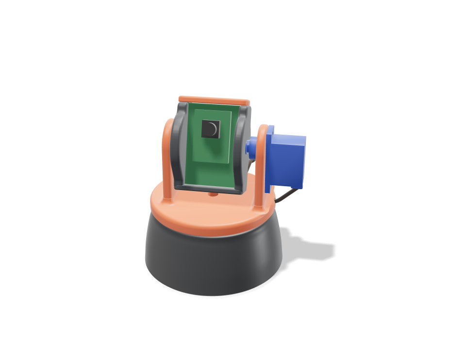
A small robotics-kit pan-tilt head for an ESP32-CAM. The base holds one SG90 by its tab screws; that servo's horn sits in a keyed pocket under the orange yoke and turns it up to 90 degrees each way. The yoke carries the second SG90, whose horn turns the camera cradle. On the other side the cradle sits on a printed pivot stub, so it is held on both sides and cannot slide off once the servo is screwed in. The board slides down edge grooves and a small cap screws on top. The tilt servo's lead snaps into a groove round the yoke, crosses to the base in a loose loop and snaps into a groove down the back, so it follows the pan without snagging. The build checks that both servos have plenty of torque for the cradle and board (well under a quarter of an SG90's stall torque), that nothing hits anything through the whole pan and tilt sweep, that the lead has enough slack for a full 90 degree pan each way, that each part goes in along a real path, and that it stands steady without screws. Printed fits, servo play and how long it lasts still need a test print.
Ask for the sizes you want to tweak, e.g. “make the width adjustable”.
Specs at the default size
Measured from the actual build on a Bambu Lab A1 in PLA. Every number updates live when you drag a slider above.
- Overall size
- 74 × 74 × 89 mm
- Parts
- 4
- Filament
- 59 g
- Print time
- 1 h 45 min
- Build plates
- 1
- Supports
- None needed
Engineering checks
- Tilt servo has the torque8.44 N.mm worst case (24.8 g cradle + cap + 10 g board, CG 1.1 mm off the axis at up to 60 deg = 0.26, plus starting a full-speed move with all mass at the 28 mm sweep radius = 8.18) vs SG90 stall 177 N.mm: under a quarter
- Pan servo has the torque15.43 N.mm to start a full-speed pan (66 g turning, I = 368 g.cm2) vs 177 N.mm stall
- Yoke stays on the pan horn1.3 N pull on a horn screw (turning group CG 3.8 mm off the pan axis, bumped x2, levered over 8 mm) vs ~40 N for an M2 self-tapper 2.5 mm into PLA, derated; the horn is also keyed into its recess for torque
- Pivot stub carries a knock0.10 MPa bending at the 6 mm stub root (half the cradle at a 5 g knock, sharp-root factor 2.3) vs 16.7 along the layers; bearing 0.03 MPa vs ~5 MPa for PLA sliding
- Arms take a 5 N knock at the top2.3 MPa at the 4.3 x 28 mm arm root (39 mm tall, bending across the layers) vs 5.0
- Tilt SG90 seats in the arm windowcase 0.2 mm clear in the window, tabs flat on the arm, two M2 tab screws; horn keyed 2.0 mm into the cradle recess; overlap 0.00 mm3
- Pan SG90 hangs on its tabs in the basetabs on the pocket ledge with two M2 screws, horn keyed into the yoke floor; overlap 0.00 mm3
- Cradle is trapped between stub and horncradle can float 0.6 mm toward the stub: the stub stays 3.1 mm in its bore and the horn stays 3.0 mm on the spline; no glue
- Board slides in and is heldPCB edges 0.7 mm deep in 1.9 mm grooves with 45 deg lead-ins, 0.3 mm side play, lifts at most 0.3 mm under the cap; header pins reach through two back windows; overlap 0.00 mm3
- Tilt sweep is clearcradle, cap and board sampled every 10 deg: clear to +/-180 deg (no contact at all; the SG90's own +/-90 deg is the limit); set range +/-60
- Pan sweep is clearyoke, tilt servo and cradle sampled at +/-45 and +/-90 deg against the base: overlap 0.00 mm3; 0.8 mm seam under the yoke
- Leads route clear, exit low at the backpan lead in the drop-in slot under the base; tilt lead snaps into a groove round the yoke rim, crosses in a service loop and snaps into a groove down the back of the base; both leave at the back within 6 mm of the desk; tightest bend 7.0 mm (>= 6 mm, 5x the 1.2 mm ribbon it bends across); overlap 0.00 mm3
- Tilt lead has slack for the whole pan96 mm free loop vs 91 mm needed at 90 deg (worst of +/-90): wrapped round the base at 36 mm radius, plus the drop and 15 mm spare
- Tilt lead is long enough240 mm from the servo to 25 mm past the back exit (12 mm behind the base) vs the 250 mm SG90 lead
- Stands steady without screws or tapetips only past 53 deg (203 g, CG 27 mm up, 1.3 mm off centre, 74 mm foot)
- pan SG90 + horn goes in23 poses along its path clear of every part.
- tilt SG90 + horn goes in16 poses along its path clear of every part.
- ESP32-CAM board goes in26 poses along its path clear of every part.
- OV2640 camera + lens goes in26 poses along its path clear of every part.
- driver: tilt tab screws goes in20 poses along its path clear of every part.
- driver: cap screws goes in20 poses along its path clear of every part.
Adjustable sizes
| Setting | Default | Range |
|---|---|---|
| Camera board width | 27 mm | 24–32 mm |
| Camera board height | 40.5 mm | 36–48 mm |
| Tilt range (each way) | 60 deg | 20–90 deg |
| Pan range (each way) | 90 deg | 30–90 deg |
| Base mounting | screws | — |
Parts list
| Part | Qty | Size (mm) | Filament | Time |
|---|---|---|---|---|
| base | 1 | 74 × 74 × 31 | 35 g | 52 min |
| yoke | 1 | 66 × 65 × 46 | 15 g | 28 min |
| cradle | 1 | 35 × 32 × 44 | 9 g | 19 min |
| top-cap | 1 | 35 × 11 × 3 | 1 g | 6 min |
How to make it
- Set the camera board width and height if yours isn't the standard 27 x 40.5 mm ESP32-CAM, then pick how far it should pan and tilt.
- Choose screws or double-sided tape for the base, and print the four parts in PLA without supports.
- Drop the pan servo into the base and screw its tabs down, then screw its horn into the yoke's pocket and press the yoke onto the servo.
- Screw the tilt horn into the cradle, slide the cradle onto the pivot stub, push the tilt servo in from outside, press its lead into the rim and base grooves, then slide the board in and screw the cap on.
Print tips
- Every part prints the way it sits, on a flat face with no supports: about 60 g and under 2 hours at 2 walls and 15% infill.
- Use 3 walls for the yoke and cradle so the small M2 self-tapping screws have plenty of plastic to bite.
- If the cradle feels stiff on the pivot stub, a light sand of the stub or a drop of dry PTFE lube frees it up.
FAQ
Does it work with a small USB webcam instead of an ESP32-CAM?
Yes, if the webcam's circuit board slides into the grooves. Set the board width and height sliders to your board and check its thickness is close to 1.6 mm.
Can the camera tilt further than 90 degrees?
The cradle itself clears all the way round, so the limit is the SG90, which turns about 90 degrees each way. The tilt slider goes up to that.
Where do the servo cables go?
The pan lead lies in a slot under the base. The tilt lead presses into a groove round the yoke's rim, hangs in a short loop at the back and presses into a groove down the back of the base, so both come out together at the back. The loop has enough slack for the full pan.
Need a shape that isn't in the catalog? Describe it in your own words with text to CAD
Comments