Ball-joint GoPro desk arm
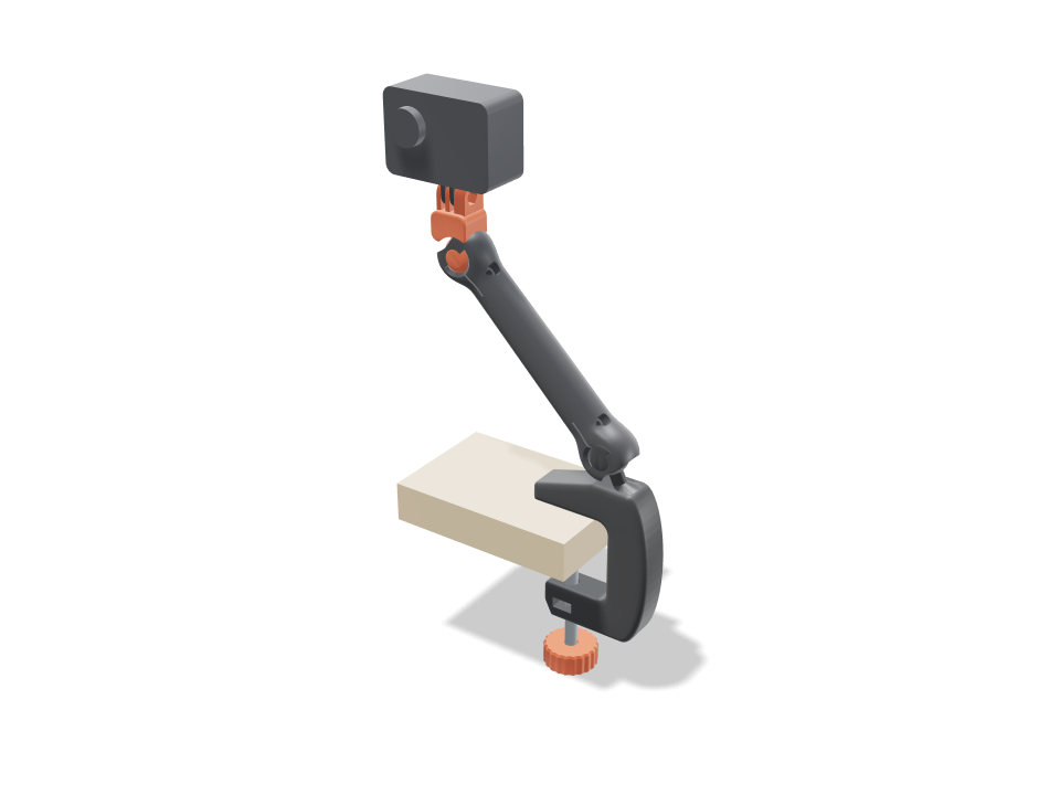
A camera arm that clamps to the edge of your desk and holds a GoPro on the standard 3-prong mount. The curved C clamp, the tapered arm and the camera head print together as one flat piece, with two ball joints already inside their sockets. Each ball sits in its socket with a small even gap and a lip that wraps past its widest point, so it turns and tilts but cannot pop out. The clamp's ball leans out over the desk and each joint tilts about 29 degrees in any direction and spins all the way round, so the arm reaches out around 45 degrees while the head keeps the camera level. One M4 screw per joint squeezes the split socket to lock the pose. The checks prove the balls print free and stay captured, how far each joint tilts before the neck meets the lip, that the clamp corners and ball necks carry the load with margin, that the screws give about four times the grip the camera needs, and that the clamp fits desks from 15 to 45 mm.
Ask for the sizes you want to tweak, e.g. “make the width adjustable”.
Specs at the default size
Measured from the actual build on a Bambu Lab A1 in pla. Every number updates live when you drag a slider above.
- Overall size
- 148 × 34 × 294 mm
- Parts
- 5
- Filament
- 73 g
- Print time
- 2 h 3 min
- Build plates
- 2
- Supports
- None needed
Engineering checks
- Flare runs into the head blockthe flare grows to 15.6 mm across, 1.5 mm inside the block's rounded edge, and enters the cup with 0.0 mm of straight neck showing
- Ball captured past the equatorsocket wraps 37 deg past the equator; opening 19.6 mm vs ball 24 mm (21.6 mm across the flats, so even panned 90 deg there is 1.0 mm of lip); pulling either joint 1.15 mm out hits the lip
- Joints print free0.35 mm surface gap all round each ball; 1.01 mm between ball and socket at the bed
- Tilt cone at the clamp jointfree to 29 deg in all four directions (0.00/0.00/0.00/0.00 mm3); the neck meets the lip by 33/33/33/33 deg; pan unlimited
- Tilt cone at the camera jointhead swings 29 deg each way on the arm (0.00/0.00/0.00/0.00 mm3)
- Aiming pose cleararm leans 45 deg out over the desk (stud 25 + joint 20), camera level and facing forward; each joint at 20 of 30 deg
- Ball neck takes a bump14.9 MPa in the 8.6 mm neck with the arm at its widest reach (55 deg from vertical), camera bumped (x2, root Kt 1.67); PLA allows 16.7 along the layers
- Pinch screw holds the pose1.23 N m of friction from an M4 snugged to 0.4 N m vs 0.28 N m from the camera and arm at widest reach (x4.4); slit 1.2 mm closes 0.70 mm to grip
- Clamp corners carry the bolt13.2 MPa inside the 7 mm corner bends (curved beam x1.70, measured sections 22 / 22 mm) at 313 N from a 0.5 N m knob twist; PLA allows 16.7 along the layers
- Clamp will not rock on the desk5.3 N m of jaw grip vs 0.95 N m from the arm sticking straight out, bumped
- Fits desks 15-45 mmM8 x 80: at 15 mm the knob sits 12 mm under the jaw, at 45 mm the pad clears the jaw by 3 mm; throat 54 mm
- GoPro fingers fit the prongs3 prongs 3 mm thick with 3.1 mm gaps (15.2 mm stack), M5 bore, nut pocket in the outer prong
- Thumb screw goes throughM5 thumb screw from the left into the captured nut
- Prints in one goclamp, arm and head lie flat in a 219 mm square turned 21 deg on the 256 mm bed, 21.6 mm tall
- Pad and knob sit on the boltpad pressed on the bolt tip against the desk underside, knob on the bolt head 22 mm under the jaw
- camera arm stays together after printingall 3 bodies are captive: none can be pulled out along any axis
- camera arm is held firmlyevery captive body is held by at least 0.8 mm (two perimeters)
- GoPro goes in35 poses along its path clear of every part.
- thumb screw goes in20 poses along its path clear of every part.
- M8 nut goes in20 poses along its path clear of every part.
- M4 x 16 pinch screw 1 goes in15 poses along its path clear of every part.
- M4 x 16 pinch screw 2 goes in15 poses along its path clear of every part.
Adjustable sizes
| Setting | Default | Range |
|---|---|---|
| Arm length (ball to ball) | 140 mm | 100–150 mm |
| Desk thickness | 25 mm | 15–45 mm |
| Ball diameter | 24 mm | 20–28 mm |
| Joint gap (each side) | 0.35 mm | 0.3–0.45 mm |
Parts list
| Part | Qty | Size (mm) | Filament | Time |
|---|---|---|---|---|
| clamp | 1 | 95 × 133 × 22 | 34 g | 50 min |
| arm | 1 | 156 × 89 × 22 | 24 g | 38 min |
| camera head | 1 | 40 × 53 × 22 | 8 g | 17 min |
| clamp pad | 1 | 26 × 26 × 6 | 2 g | 7 min |
| clamp knob | 1 | 34 × 34 × 14 | 5 g | 12 min |
How to make it
- Set your desk thickness and the arm length you want, then pick a ball size: bigger balls tilt a little further and grip harder.
- Print the arm in one go, back face down with no supports, then print the knob and pad. Leave the joint gap at 0.35 mm unless a test print comes out tight or loose.
- Free each ball with a firm twist, fit the two M4 screws and nuts, and press the M8 bolt head into the knob and an M8 nut into the clamp slot (the build names the bolt length, M8 x 80 at the default size).
- Clamp it to the desk, slide your GoPro fingers into the prongs with a thumb screw, aim it, then snug the M4 screws to hold the pose.
Print tips
- Turn supports off: support material would print into the joint gaps and fuse the balls.
- PLA or PETG with 3 walls works well; use a smooth PEI plate and check the first layer, since a squashed first layer is the most likely way to stick a ball to its socket.
- If the joints feel stiff after freeing them, work each one through its full range a few times before you add the camera.
FAQ
Will it hold my GoPro without drooping?
Yes once the M4 pinch screws are snug. The checks show about four times the friction needed to hold a GoPro with the arm at its widest reach. With the screws loose the joints move freely, which is how you aim it.
Can I use it with a phone?
The tip is a standard GoPro 3-prong mount, so any phone clip with GoPro fingers fits. This design does not include the phone clip itself.
What hardware do I need?
One M8 bolt and nut for the clamp (M8 x 80 at the default size), two M4 screws with nuts for the joints (M4 x 16 at the default size), and a GoPro thumb screw with an M5 nut for the camera. The build names the exact lengths for your sliders.
Need a shape that isn't in the catalog? Describe it in your own words with text to CAD
Comments