Snap fit design for 3D printing: the one formula that stops them snapping off
Most printed snap fits fail at the first push, right where the arm meets the wall. It isn’t bad luck. The arm was asked to bend further than the plastic can stretch, and one line of arithmetic would have said so.
Short answer
Size a cantilever snap arm so its bending strain stays below what the plastic tolerates: strain = 1.5 × thickness × deflection ÷ length². Aim for about 2% in PLA and 3–4% in PETG, and halve those if the arm bends across its layers. A 1.5 mm thick PLA arm that has to move 1 mm needs to be about 11 mm long; in PETG, about 8 mm. Print the arm lying flat, give its root a fillet at least half its thickness, and use a 30° lead-in.
You design a neat little box with snap-fit clips, print it, line up the lid and push. There is a small dry crack, and a clip lies on the table. The rest of the clips now look at you with suspicion.
The clip didn’t break because PLA is weak. It broke because the design asked it to bend further than PLA can stretch, and the place it broke, right at the root, is the exact spot a single formula predicts. Here is the formula, two worked examples, and the printing details that decide the rest.
Why printed snap fits break
A snap fit is a springy arm with a hook on the end. To go together, the hook must ride over a ledge, so the arm bends out of the way and then springs back behind it. While it is bent, the outside surface of the arm stretches. That stretch, called strain, is largest where the arm joins the part.
Every plastic tolerates a certain strain before it cracks or stays bent. A clip designed without checking that number is a coin flip. Three things make the odds worse on a printer:
- PLA is stiff and brittle, so its safe strain is low.
- Printed parts are weaker across their layers than along them, sometimes by half.
- A square inside corner at the root of the arm concentrates the strain right where it already peaks.
The formula
For a straight arm of constant thickness, fixed at one end, the peak strain is:
strain = 1.5 × h × y ÷ L²
h is the arm’s thickness in the direction it bends, y is how far the hook has to move to clear the ledge (the overlap), and L is the length of the arm from its root to the hook. Use the same units for all three.
Read it like a set of levers. Strain grows with thickness and with overlap, and it falls with the square of length. So a longer arm is by far the strongest fix: make it 40% longer and the strain halves. A thicker arm, which feels like the obvious fix, makes things worse.
Turned around, it tells you the shortest arm that is safe:
minimum length = √(1.5 × h × y ÷ allowed strain)
| Material | Arm printed flat (bends along the layers) | Arm printed upright (bends across the layers) |
|---|---|---|
| PLA | about 2% | about 1% |
| PETG | 3–4% | about 1.5–2% |
| ABS / ASA | 3–4% | about 1.5–2% |
| Nylon (PA) | 4–6% | about 2–3% |
Two worked examples
A PLA lid clip
The arm is 1.5 mm thick and the hook overlaps its ledge by 1 mm. In PLA, printed flat, we allow 2%:
L = √(1.5 × 1.5 × 1 ÷ 0.02) = √112.5 ≈ 10.6 mm
So the arm needs to be at least 11 mm long. The instinctive design, a stubby 5 mm arm, would see about 9% strain, four times what PLA tolerates. That is the crack you heard.
The same clip in PETG
PETG tolerates more. At 3.5%, the same arm needs √(2.25 ÷ 0.035) ≈ 8.0 mm. If a design has no room for a long arm, switching filament is a legitimate engineering fix.
| Arm thickness | 0.5 mm overlap | 1 mm overlap | 1.5 mm overlap |
|---|---|---|---|
| 1.0 mm | 6.1 mm | 8.7 mm | 10.6 mm |
| 1.5 mm | 7.5 mm | 10.6 mm | 13.0 mm |
| 2.0 mm | 8.7 mm | 12.2 mm | 15.0 mm |
Print the arm lying down
Printed plastic has a grain. Along a layer, the plastic is one continuous line and nearly as strong as the raw filament. Across layers, it is only as strong as the bond between one layer and the next.
So orient the part so the arm bends along its layers. In practice that means the arm lies flat on the bed or stands so its bending direction is parallel to the bed. An arm that stands straight up and bends toward or away from you peels its layers apart at the root, and needs half the strain (or twice the thought) to survive.
When the box’s shape forces upright clips, put them on a separate part printed flat and join it with a screw, or design a different joint.
Fillets, tapers and hook angles
Round the root
Give the inside corner where the arm meets the wall a fillet at least half the arm’s thickness: 0.75 mm for a 1.5 mm arm. It spreads the peak strain over more plastic and costs nothing.
Taper the arm
An arm that is thick at the root and thinner toward the hook, down to about half, bends more evenly along its length, so its peak strain drops for the same overlap. It is the one change that makes an arm both springier and tougher.
Choose the hook angles
- Lead-in (the side you push over): about 30°. Steeper, and assembly needs brute force.
- Retaining face (the side that holds): 90° makes a permanent joint that must be released by hand. About 45° makes one that pulls apart with force and can be reused.
Make the hook itself at least as thick as the arm, and don’t forget it has to print: a retaining face that overhangs by more than about 45° needs to face upward or be chamfered.
Clearance and the click
Two kinds of gap live in a snap fit. The surfaces that slide past each other, the walls of the lid and box, want a normal sliding clearance of 0.2–0.3 mm total so nothing binds. The hook overlap is not a clearance at all. It is the deflection y in the formula, and it is what holds the joint closed. More overlap holds tighter and strains the arm more.
For most clips, 0.8–1.2 mm of overlap gives a positive click without overdoing it. The tolerance guide shows how to find your printer’s real sliding clearance.
Test one arm before the whole box
Cut one clip and its catch out of the design as a small test piece, print it in the filament you’ll use, and snap it ten times. That takes a few grams and a few minutes, and it tells you more than any table. In Loftsmith you can circle the clip in the Studio and print just that area as a test piece.
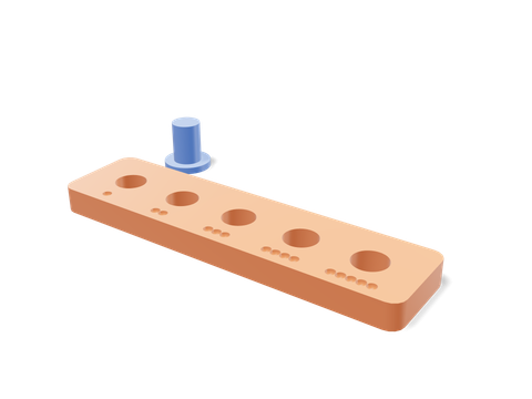 Tolerance testerFind the sliding clearance your printer really makes before you set the lid gap.71 × 35 × 10 mm · 5 g · 21 min
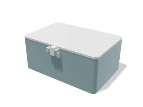 Compact locking-pin boxA box with a checked 0.25 mm lid gap and a removable locking pin you can study or reuse.120 × 88 × 52 mm · 91 g · 2 h 17 min
Questions people ask
Is PLA good for snap fits?
It works if you design for it. PLA is stiff and brittle, so it tolerates only about 2% strain in a flat-printed arm. Make the arm longer and thinner than instinct suggests, or use PETG, which is tougher and forgives roughly twice the strain.
How thick should a 3D printed snap fit be?
Thin enough to bend: usually 1–2 mm. Thickness is the easiest way to break a snap arm, because strain grows in direct proportion to it. If an arm needs to be stiffer, make it wider, not thicker.
What tolerance do snap fits need?
Around 0.2–0.3 mm of total clearance on the surfaces that slide past each other, and none on the hook itself: the hook’s overlap (the deflection) is what holds the joint shut.
Why does my snap fit break at the base?
Strain peaks at the root of the arm. A sharp inside corner concentrates it further, and an arm printed upright bends across its weakest layer line. Add a fillet at least half the arm’s thickness and print the arm flat on the bed.
Sources and method
The numbers come from Loftsmith’s CAD engine, which uses them to design and check every part it builds, and from the manufacturer and reference sources below. Every figure is checked against those sources and the engine’s own geometry. Found a mistake? Email [email protected] and we’ll fix it.