Screw holes for 3D printing: M2–M6 clearance, tap and nut-trap sizes
Every functional print ends in a screw. The sizes below are the ones Loftsmith’s CAD engine uses for every part it designs, with the reasoning behind each, so you can use them in any CAD program.
Short answer
For a screw to pass through, model the hole at ISO 273 medium clearance: M2 2.4 mm, M2.5 2.9 mm, M3 3.4 mm, M4 4.5 mm, M5 5.5 mm, M6 6.6 mm. For a screw that cuts its own thread in the plastic, use about 85% of the screw diameter (M3 2.6 mm). Hex nut traps want the nut’s width across flats plus 0.3 mm (M3: 5.8 mm). If the joint will be taken apart more than a few times, use a heat-set insert instead.
The part is perfect until the screw goes in. Then the head sits proud because the counterbore is shallow, or the screw binds halfway because the hole printed small, or the nut you meant to trap turns with the screw. None of these are hard problems. They are easy to forget, one hole at a time.
Here is the complete set of numbers, the reason behind each, and the few rules that keep screw holes working in every orientation.
The chart
| Screw | Clearance hole | Self-tap hole | Socket head counterbore | Hex nut trap (across flats) | Nut trap depth | Heat-set insert hole |
|---|---|---|---|---|---|---|
| M2 | 2.4 | 1.7 | Ø4.4 × 2.2 | 4.3 | 1.9 | 3.2 |
| M2.5 | 2.9 | 2.2 | Ø5.1 × 2.7 | 5.3 | 2.3 | 3.6 |
| M3 | 3.4 | 2.6 | Ø6.3 × 3.2 | 5.8 | 2.7 | 4.1 |
| M4 | 4.5 | 3.5 | Ø7.8 × 4.2 | 7.3 | 3.5 | 5.6 |
| M5 | 5.5 | 4.4 | Ø9.3 × 5.2 | 8.3 | 5.0 | 6.4 |
| M6 | 6.6 | 5.3 | Ø10.8 × 6.2 | 10.3 | 5.5 | 8.0 |
screwHole(), nutTrap() and insertHole() in Loftsmith’s CAD engine, tuned for a 0.4 mm nozzle. They are starting points: print one test hole in your filament before you print a large part.Clearance holes
A clearance hole lets the screw pass through one part so it can clamp it to another. The screw should drop through without threading into the plastic. The sizes above are the ISO 273 “medium” clearance series: 3.4 mm for M3, 4.5 mm for M4, and so on.
That may look generous. It is on purpose. A 3.2 mm hole modelled for an M3 screw usually prints at about 3.0–3.1 mm, which is a thread-cutting hole, not a clearance hole, and the screw drags. Medium clearance absorbs the 0.1–0.2 mm that FDM takes off small holes and still leaves room for two holes that don’t line up perfectly.
If holes must line up precisely, such as a motor mount, don’t shrink the holes. Make one part’s holes round and let the other part’s holes be short slots, so the screw pattern can adjust by a millimetre.
Screwing straight into plastic
For a part you assemble once, the simplest joint is a screw threaded straight into a slightly undersized hole. The screw cuts or forms its own thread.
self-tap hole ≈ 0.85 × screw diameter
A few things decide whether it holds:
- Walls, not infill. The thread forms only in solid plastic. Set at least three perimeters for parts with screw holes, and leave 2 mm or more of material around each hole in the model.
- Screw type. Screws made for plastic (wide-pitch, sharp threads, often sold as “plastic” or “PT” screws) grip much better than machine screws, and are less likely to split the part.
- Engagement. Aim for thread depth of at least two to three screw diameters: 6–9 mm for M3.
- Stop when it seats. Plastic threads strip easily. Tighten until the head touches, then a quarter turn more.
Printed threads wear out after a few assemblies. If a joint will be opened regularly, use a heat-set insert or a trapped nut instead.
Counterbores and countersinks
A counterbore is a wider, flat-bottomed pocket that lets a socket head sit below the surface. Model it 0.6 mm wider than the head’s diameter (5.7 mm heads get a 6.3 mm pocket) and 0.2 mm deeper than the head, so the head is fully hidden even if the first layers squash a little.
A countersink is a cone for flat-head screws. Printed cones come out rough, so make them slightly bigger than the head and accept that a flat head will seat a hair low. Countersinks on the top surface of a part print cleanly; countersinks on the bottom face print as an overhang and look worse. Where you can choose, put the flat head on top.
Nut traps
A nut trap is a hexagonal pocket that holds a standard nut so it can’t turn. It gives you a real metal thread with no heat and no special parts, and it is the best joint for parts you take apart often.
- Model the width across the flats, not across the corners. An M3 nut is 5.5 mm across its flats; the pocket is 5.8 mm.
- Make it 0.3 mm deeper than the nut so the nut sits below the surface.
- Put a flat toward the bed. A hexagon printed with a point up has a sharp, bridged corner at the top. A flat on top prints as a short straight bridge.
- Side-loaded traps, a slot the nut slides into from the edge, work where the nut can’t go in along the screw axis. Make the slot the same across-flats width and add a little extra length so the nut can reach the hole.
If a nut won’t go in, don’t melt it in with a soldering iron. That is what inserts are for. Widen the pocket by 0.1 mm and reprint the test.
Horizontal holes and the sagging roof
A hole that runs parallel to the bed has a roof, and the printer draws that roof over nothing. It sags, so the hole ends up egg-shaped and the screw drags or won’t go in.
Shape the top of the hole to avoid the bridge. A teardrop profile (a circle with a 45° point on top) prints without support; so does a circle with a small flat cut across its top. Loftsmith’s print check colours overhanging faces, so a sagging hole roof shows up on screen before it shows up in plastic.
Clearance, tap, nut or insert?
| Joint | Strength | Survives reassembly | Extra parts | Best for |
|---|---|---|---|---|
| Self-tapping into plastic | Good | A few times | None | Covers and parts assembled once |
| Trapped hex nut | Very good | Indefinitely | A nut | Frequent disassembly, high clamping force |
| Heat-set insert | Very good | Indefinitely | An insert and a soldering iron | Enclosures, standoffs, clean outside surfaces |
| Through-bolt with nut | Best | Indefinitely | A nut and washer | Loaded brackets and mounts |
When you are unsure, ask what happens on the tenth assembly. If the answer is “there won’t be one,” tap straight into the plastic. If there will be, use metal threads.
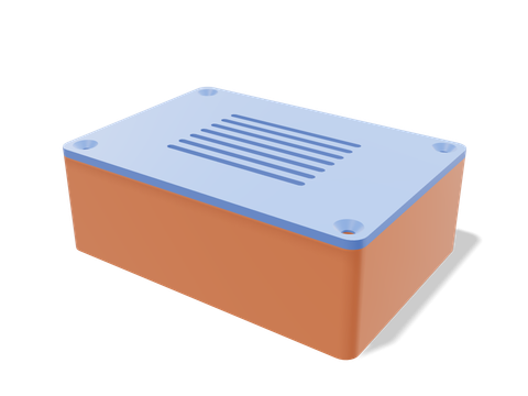 Electronics enclosureA board enclosure that uses these hole sizes for its standoffs, lid screws and ports.96 × 67 × 33 mm · 49 g · 1 h 15 min
Questions people ask
What size hole for an M3 screw in a 3D print?
3.4 mm if the screw should pass through freely, 2.6 mm if the screw should cut its own thread into the plastic, and 4.0–4.1 mm if you are fitting an M3 heat-set insert.
Can you screw directly into a 3D printed part?
Yes, with a pilot hole of about 85% of the screw diameter and at least three perimeters around it. It holds well for a handful of assemblies; after that the plastic threads wear out, and a heat-set insert or captive nut is the better choice.
How big should a nut trap be for an M3 nut?
An M3 nut is 5.5 mm across the flats, so model a hexagonal pocket 5.8 mm across the flats and about 2.7 mm deep (nut height plus 0.3 mm). Orient one flat toward the bed, and remember the model needs the across-flats size, not the across-corners size.
Why do my horizontal screw holes come out oval?
The top of a hole printed on its side is a short bridge, and it sags. Make the hole teardrop-shaped or give it a flat roof so the printer never bridges a curve, or drill it out after printing.
Sources and method
The numbers come from Loftsmith’s CAD engine, which uses them to design and check every part it builds, and from the manufacturer and reference sources below. Every figure is checked against those sources and the engine’s own geometry. Found a mistake? Email [email protected] and we’ll fix it.