Heat-set insert hole sizes: an M2–M6 chart for 3D printing
A heat-set insert turns a printed part into something you can unscrew a hundred times. It only works if the hole is right: too small and the wall bulges, too big and the insert spins the first time you tighten a screw.
Short answer
Model the hole at the insert maker’s recommended diameter, plus about 0.1 mm if your printer prints holes small. For common short brass inserts that means roughly M2 3.2 mm, M2.5 3.6 mm, M3 4.0–4.1 mm, M4 5.6 mm, M5 6.4 mm and M6 8.0 mm. Make the hole about 1 mm deeper than the insert, leave at least 1.6 mm of wall (three perimeters is better), and press the insert in near your printing temperature.
Screw a steel bolt straight into printed plastic and it holds, the first time. By the fifth time the thread you cut in the plastic has turned to fluff, and the screw spins in place. A heat-set insert fixes that for good. It is a small knurled brass sleeve that you melt into a hole with a soldering iron. The plastic flows into the knurls, freezes, and from then on you have a metal thread in a plastic part.
Everything depends on the hole. This guide gives you the sizes, and then shows you how to make them right for your own printer in one small print.
The chart
| Thread | Hole to model | Typical insert length | Hole depth | Wall around it |
|---|---|---|---|---|
| M2 | 3.2 mm | 4.0 mm | 4.8 mm | ≥ 1.6 mm, ideally 3 perimeters |
| M2.5 | 3.6 mm | 4.5 mm | 5.3 mm | ≥ 1.6 mm, ideally 3 perimeters |
| M3 | 4.1 mm | 5.7 mm | 6.5 mm | ≥ 1.6 mm, ideally 3 perimeters |
| M4 | 5.6 mm | 8.1 mm | 8.9 mm | ≥ 1.6 mm, ideally 3 perimeters |
| M5 | 6.4 mm | 9.5 mm | 10.3 mm | ≥ 1.6 mm, ideally 3 perimeters |
| M6 | 8.0 mm | 12.7 mm | 13.5 mm | ≥ 1.6 mm, ideally 3 perimeters |
insertHole() in its script language). They follow the manufacturers’ recommendations, with M3 raised from 4.0 to 4.1 mm because printed holes usually come out 0.1–0.2 mm small. Always check the datasheet of the inserts you bought.If your inserts are the long or the short variant of a size, keep the diameter and change the depth. The diameter belongs to the insert’s outside shape, not its length.
Why the maker’s number is only the start
The makers of the popular M3 × 5.7 mm inserts recommend a 4.0 mm hole. That number is right, for a hole that really is 4.0 mm. Your printer may not print one. A small vertical hole on a typical FDM printer comes out 0.1–0.2 mm under its CAD size, for reasons covered in the tolerance guide: polygon facets, squished lines bulging inward, and elephant foot at the bottom.
You can tell which side of the line you are on by what happens when you press:
- Hole too small: the surface around the hole rises in a ring, the insert takes a lot of force, and thin walls crack or bulge outward.
- Hole too big: the insert sinks in with no resistance, sits crooked, and spins when you tighten a screw.
- Right: it needs gentle, steady pressure, a small collar of plastic wells up around the top, and the insert ends flush and square.
Some inserts are tapered, so the bottom of the insert is narrower than the top. They start easily and straight, which is a real advantage when you press by hand. Model the hole to the maker’s number for the wide end, or taper the hole to match if your CAD program makes that easy.
Depth and wall thickness
Make the hole deeper than the insert. As the insert goes in, it pushes molten plastic ahead of it. If the hole is exactly insert-length, that plastic has nowhere to go, fills the thread and stops the screw. About 1 mm of extra depth gives it a place to collect. Loftsmith adds 0.8 mm to every insert hole.
Give it solid wall. The insert holds because melted plastic grips its knurls. If the wall around the hole is thin, the knurls grip infill and air. Set at least three perimeters (walls) in the slicer for parts with inserts, and leave at least 1.6 mm of material around the hole in the model. Loftsmith’s standoff posts are the insert diameter plus 3.2 mm, which leaves exactly that. Where the insert will carry real load, such as a bracket screwed to a wall, go thicker.
Pressing inserts in straight
A crooked insert makes a crooked screw, and a crooked screw pulls the insert back out. A few habits keep it straight:
- Use the right tip. A tip made for inserts has a shoulder that holds the insert square. A pointed soldering tip will do in a pinch, but it tilts easily.
- Set the temperature near your printing temperature. About 220 °C works for PLA. Hotter lets the insert sink too fast and drag molten plastic with it; colder means you end up forcing it, which cracks walls.
- Let the heat do the work. Rest the insert on the hole, let it warm for a couple of seconds, then press with light, steady pressure. Stop just before it’s flush.
- Finish flat. Take the iron away and press the insert the last fraction of a millimetre with something flat and cold, like the side of a metal ruler. It sets flush and square as it cools.
If you use a drill press or a dedicated insert press to hold the iron vertical, all of this becomes easy, and it is worth building one if you do more than a handful of inserts a month.
PLA, PETG and other filaments
PLA takes inserts well and is the easiest to start with. PETG holds them just as well but softens over a wider temperature range, so it needs a slightly hotter tip, more patience and a clean tip, because it sticks. ABS and ASA are the most forgiving of all; they melt cleanly and grip hard. Very soft filaments such as TPU are the wrong material for inserts; use a captive nut instead.
Whatever the filament, print the test block in that filament. The same hole size can be perfect in PLA and a little tight in PETG.
When a screw straight into plastic is enough
Inserts are not always worth it. If a cover goes on once and stays on, a self-tapping screw in a pilot hole of about 85% of the screw diameter (2.6 mm for M3) is simpler and plenty strong. Use inserts where a joint will be opened again and again, where the screw carries load, or where you need a clean metric thread for a standard machine screw. The screw hole guide covers the other options, including nut traps.
Settle it with a test block
The insert tester puts five holes side by side, stepping 0.15 mm around the chart size, so for M3 you get 3.8, 3.95, 4.1, 4.25 and 4.4 mm. One print and five inserts tell you which size your printer and filament want.
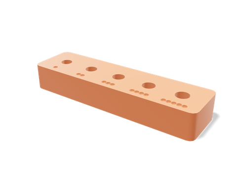 Heat-set insert testerFive insert holes around the catalog size, M2 to M5, with adjustable step and wall.60 × 16 × 9 mm · 5 g · 11 min
Press an insert into each hole, let them cool, then drive a screw into each one and tighten it firmly. Pick the smallest hole that took the insert without a bulge. If two look equally good, pick the smaller: it will grip harder.
Then write the number down, because you will need it for every enclosure you design. If you design in Loftsmith, tell it (“M3 inserts: 4.0 mm hole”) and every standoff it models uses your number.
Questions people ask
What size hole for an M3 heat-set insert?
About 4.0 mm for the common M3 × 5.7 mm brass insert, as its makers recommend. Loftsmith models 4.1 mm because FDM holes usually print 0.1–0.2 mm small. Make the hole about 6.5 mm deep and print a test block in your filament to confirm.
What temperature should the soldering iron be for heat-set inserts?
Start near the filament’s printing temperature: around 220 °C for PLA and a little hotter for PETG. Too hot and the plastic turns runny and the insert sinks crooked; too cold and you end up forcing it.
How much wall do heat-set inserts need?
At least 1.6 mm around the hole, and ideally three or more perimeters, so the knurls bite into solid plastic rather than infill. Loftsmith’s standoffs leave 1.6 mm; its test block leaves 3.5 mm.
Can I use heat-set inserts in PETG?
Yes. PETG holds inserts well; it just needs a slightly hotter iron than PLA and a little patience, because it softens over a wider range and can stick to the tip.
Sources and method
The numbers come from Loftsmith’s CAD engine, which uses them to design and check every part it builds, and from the manufacturer and reference sources below. Every figure is checked against those sources and the engine’s own geometry. Found a mistake? Email [email protected] and we’ll fix it.