3Dプリントできる全翼機ジェネレーター
誰もが持っているパーツを前提に設計しました。推進式の2212モーター、30 A ESC、4S 1500 mAh LiPo(または3S 2200)、MG90Sサーボ2個、小型受信機。翼型は後退角・テーパー・ねじり下げを付けたMH45クラスの反転キャンバー翼です。翼端のウィングレットがヨー方向の安定を生みます。LW-PLAのパネルは、CADでモデリングした交差ラティスで補強した中空スキンで、カーボンスパーとジョイナーに通します。すべての部品がモデル内に配置されています。バッテリーはスナップ式ハッチの下のポッドに、各サーボは翼下のポケットにネジ留めするPETGフレームに固定され受信機まで配線チャネルが通り、モーターはドライバーがネジに届くよう引き抜けるテールコーンに、ESCは風が冷やす翼下のくぼみに収まります。各パーツは実際の体積と素材から各部品とあわせて重さを算出し、バッテリーを重心位置までスライドできることをチェックします。各パーツは役割に合った素材でプリントします。重さが重要な部分はLW-PLA、熱を持つモーターとESCを支えるテールコーン・スナップハッチ・サーボフレームはPETG、薄いウィングレットはPLA、柔軟なヒンジはTPU。「使う」を押すと、ピッチとロールでエレボンが動く様子が見られ、組み立ては実際の順番で再生されます。
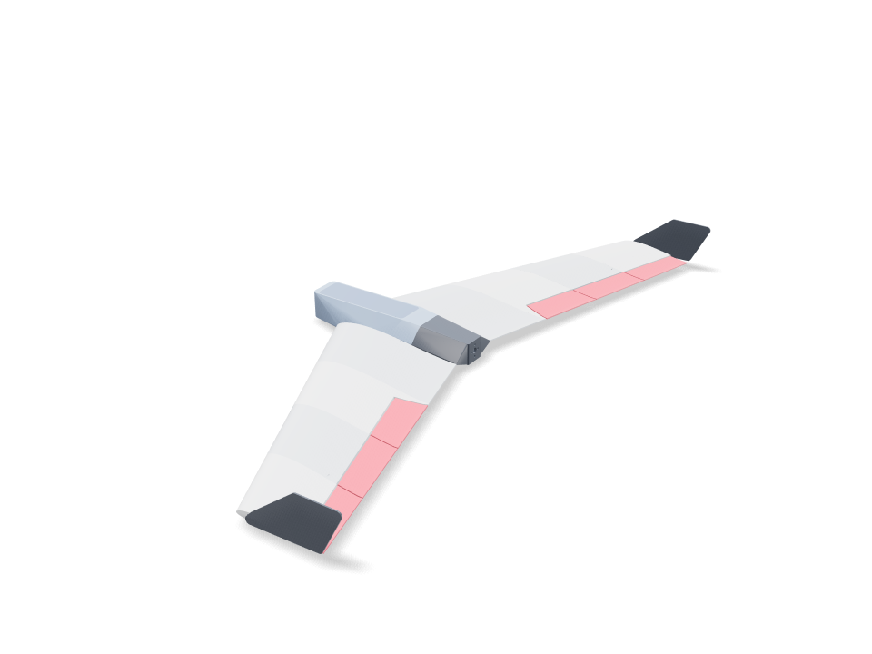
Ask for the sizes you want to tweak, e.g. “make the width adjustable”.
デフォルトサイズでの仕様
Bambu Lab A1でPLAを使った実際のビルドから計測。上のスライダーを動かすと、すべての数値がリアルタイムで更新されます。
- 全体サイズ
- 436 × 994 × 86 mm
- パーツ数
- 36
- フィラメント
- 427 g
- プリント時間
- 21 h 50 min
- プレート数
- 3
- サポート
- 一部のパーツで必要
工学チェック
チェック名とパラメーター名はCADエンジンから直接出力されるため、英語で表示されます。
- Modeled lattice in panel 1 R13342.5 mm3 of internal CAD material; not slicer infill or a strength qualification
- Modeled lattice in panel 2 R11146.3 mm3 of internal CAD material; not slicer infill or a strength qualification
- Modeled lattice in elevon 2 RInterior webs remain after the control-surface crop; physical stiffness is unverified
- Modeled lattice in panel 3 R9231.5 mm3 of internal CAD material; not slicer infill or a strength qualification
- Modeled lattice in elevon 3 RInterior webs remain after the control-surface crop; physical stiffness is unverified
- Modeled lattice in panel 4 R6908.2 mm3 of internal CAD material; not slicer infill or a strength qualification
- Modeled lattice in elevon 4 RInterior webs remain after the control-surface crop; physical stiffness is unverified
- Modeled lattice in panel 1 L13342.5 mm3 of internal CAD material; not slicer infill or a strength qualification
- Modeled lattice in panel 2 L11146.3 mm3 of internal CAD material; not slicer infill or a strength qualification
- Modeled lattice in elevon 2 LInterior webs remain after the control-surface crop; physical stiffness is unverified
- Modeled lattice in panel 3 L9231.5 mm3 of internal CAD material; not slicer infill or a strength qualification
- Modeled lattice in elevon 3 LInterior webs remain after the control-surface crop; physical stiffness is unverified
- Modeled lattice in panel 4 L6908.2 mm3 of internal CAD material; not slicer infill or a strength qualification
- Modeled lattice in elevon 4 LInterior webs remain after the control-surface crop; physical stiffness is unverified
- Battery trims the balance pointbalance at 18% MAC = 128 mm behind the root LE (static margin ~7% to a ~25% MAC neutral point); the battery reaches it with its front -35 mm behind the root LE (trim range 123-134 mm)
- Hatch snaps without cracking0.75% peak strain in a 12 mm PETG arm over a 0.6 mm hook (keep under half of PETG's 10% elongation)
- Wing loading ≤ 45 g/dm²44.8 g/dm² at 794 g all-up (printed parts 452 g from their volumes; 4S 1500 175 g)
- Stall speed ≤ 10 m/s (CL 0.8)9.5 m/s — hand-launchable
- Thrust for a hand launchthrust/weight 1.13 with 900 g static thrust (typical of a 2212 ~1000 KV on 4S with an 8x4.5 prop; read your motor's chart and set it)
- Winglets give yaw stabilitytwo tip plates, 7.0% of the wing area
- Elevons have authority16% of the wing area, ±15 deg throw on TPU hinges
- Pushrods run clear under the wing1.2 mm wire from each servo horn to its control horn, straight and level
- Linkage gives the full elevon throwcontrol horn 15.4 mm under the hinge line, servo horn 16 mm: +/-15 deg of elevon needs +/-14 deg of servo travel (under 45)
- TPU hinges bend within TPU's range21% peak bending strain in the 0.8 mm strip at +/-15 deg, bending across a 0.5 mm gap on the pivot line (keep under a tenth of TPU's 400%)
- Winglet pegs fit the tip airfoiltip airfoil 11.6 mm thick at the pegs for 5 mm square pegs (1.2 mm wall each side)
- Servos screwed down, not gluedeach MG90S: two M2 tab screws into 6 mm PETG ears (2 x screw diameter of thread), frame held by two M2 screws into heat-set inserts in wing columns
- Servos fit under the top skinMG90S (catalog proxy) on its side in a pocket opening under the wing; at least 1 mm of top skin left above it
- Servo plugs pass the wire channel10.2 mm channel from each servo to the receiver bay for a 8 x 4.2 mm plug
- Prop clears the trailing edge22 mm between the 8 inch prop and the nearest trailing edge; use a folding prop or land on grass (a pusher prop sits below the belly)
- receiver goes in30 poses along its path clear of every part.
- servo lead R goes in87 poses along its path clear of every part.
- servo lead L goes in87 poses along its path clear of every part.
- ESC goes in15 poses along its path clear of every part.
- 2212 motor + 8x4.5 prop goes in20 poses along its path clear of every part.
- driver: motor screws (bench) goes in30 poses along its path clear of every part.
- driver: tail cone screws goes in20 poses along its path clear of every part.
- MG90S servos goes in20 poses along its path clear of every part.
- MG90S onto its frame (bench) R goes in15 poses along its path clear of every part.
- driver: servo tab screws (bench) R goes in20 poses along its path clear of every part.
- MG90S onto its frame (bench) L goes in15 poses along its path clear of every part.
- driver: servo tab screws (bench) L goes in20 poses along its path clear of every part.
- driver: servo frame screws goes in20 poses along its path clear of every part.
- carbon joiner 8 mm goes in125 poses along its path clear of every part.
- carbon spar R goes in245 poses along its path clear of every part.
- carbon spar L goes in245 poses along its path clear of every part.
- battery goes in30 poses along its path clear of every part.
調整できる寸法
| 設定 | 初期値 | 範囲 |
|---|---|---|
| Half-span (per wing) | 450 mm | 250–500 mm |
| Root chord | 220 mm | 140–240 mm |
| Tip chord | 130 mm | 80–180 mm |
| LE sweep | 25 ° | 15–35 ° |
| Washout | 3 ° | 0–5 ° |
| Skin thickness | 0.9 mm | 0.6–1.6 mm |
| Lattice web thickness | 1 mm | 1–2 mm |
| Diagonal lattice pitch | 60 mm | 30–90 mm |
| Panels per wing | 4 | 2–6 |
| Carbon spar OD | 8 mm | 5–10 mm |
| Battery | 4S 1500 | — |
| Motor static thrust (from its chart) | 900 g | 400–1600 g |
パーツリスト
| パーツ | 数量 | サイズ(mm) | フィラメント | 時間 |
|---|---|---|---|---|
| centre-section | 1 | 129 × 45 × 90 | 32 g | 1 h 36 min |
| nose | 1 | 44 × 90 × 77 | 17 g | 54 min |
| tail cone | 1 | 43 × 90 × 93 | 43 g | 1 h 8 min |
| hatch | 1 | 162 × 47 × 14 | 16 g | 25 min |
| servo frame R | 1 | 47 × 24 × 14 | 2 g | 8 min |
| panel-1-R | 1 | 250 × 23 × 113 | 42 g | 2 h 3 min |
| panel-2-R | 1 | 198 × 21 × 113 | 31 g | 1 h 34 min |
| elevon-2-R | 1 | 75 × 10 × 108 | 7 g | 32 min |
| control horn R | 1 | 21 × 16 × 2 | 0 g | 5 min |
| panel-3-R | 1 | 165 × 20 × 113 | 27 g | 1 h 24 min |
| elevon-3-R | 1 | 75 × 9 × 111 | 7 g | 32 min |
| panel-4-R | 1 | 148 × 18 × 113 | 23 g | 1 h 14 min |
| elevon-4-R | 1 | 68 × 8 × 108 | 5 g | 29 min |
| servo frame L | 1 | 47 × 24 × 14 | 2 g | 8 min |
| panel-1-L | 1 | 250 × 23 × 113 | 42 g | 2 h 3 min |
| panel-2-L | 1 | 198 × 21 × 113 | 31 g | 1 h 34 min |
| elevon-2-L | 1 | 75 × 10 × 108 | 7 g | 32 min |
| control horn L | 1 | 21 × 16 × 2 | 0 g | 5 min |
| panel-3-L | 1 | 165 × 20 × 113 | 27 g | 1 h 24 min |
| elevon-3-L | 1 | 75 × 9 × 111 | 7 g | 32 min |
| panel-4-L | 1 | 148 × 18 × 113 | 23 g | 1 h 14 min |
| elevon-4-L | 1 | 68 × 8 × 108 | 5 g | 29 min |
| winglet-R | 1 | 145 × 72 × 8 | 15 g | 24 min |
| winglet-L | 1 | 145 × 72 × 8 | 15 g | 24 min |
| hinge strip (TPU) | 12 | 22 × 24 × 1 | 0 g | 5 min |
作り方
- プリンターを選び、翼幅・翼弦・後退角を設定します。重心、翼面荷重、失速速度、推力のチェックがドラッグのたびに再計算されます。
- モーターの静止推力をデータ表から入力し、バッテリーを選びます。
- パネル、エレボン、センター、ノーズはLW-PLA、テールコーン、ハッチ、サーボフレームはPETG、ウィングレットはPLA、ヒンジストリップはTPUでプリントします。
- 1.75 mmフィラメントを位置決めピンにして、パネルをカーボンスパーとジョイナーに接着します。ノーズを接着します。各ウィングレットには四角いダボが2つあるので、翼端リブの対応するポケットに接着剤を1滴入れて奥まで押し込みます。
- ヒンジ:各ヒンジ面の壁の中央に薄いポケットが2つあります。翼側とエレボン側のポケットに瞬間接着剤を1滴ずつ入れ、TPUストリップを翼に半分差し込み、上からエレボンをスライドさせ、固まるまで0.5 mmの隙間を保ちます。ストリップは隙間でドアのヒンジのように曲がります。
- リンケージ:PETGのコントロールホーンを各エレボン下のスロットに接着し、サーボホーンを下向きに取り付け、両端をZベンドした1.2 mmワイヤーでつなぎます。ホーンの穴はヒンジラインの下にあるので、上下の舵角は同じになります。
- 作業台で各サーボの耳をPETGフレームにネジ留めし、フレームごと下からポケットに入れ、翼の柱に埋め込んだヒートセットインサートにM2ネジ2本を下から締めます。配線をチャネルからベイへ通します。
- 長いドライバーで開いた前面からモーターをテールコーンにネジ留めし、コーンのタングにM3インサートを2つ埋め込み、胴体に差し込んで下からM3ネジ2本で固定します。
- ハッチを両側がカチッと鳴るまで押し込み、重心チェックの位置になるまでバッテリーをスライドさせます。
プリントのコツ
- LW-PLAは230〜250 °Cで発泡し、重さが約半分になります。先にフローを校正しましょう。
- パネルは付け根リブを下にして立て、インフィル0%でプリントします。内部ラティスはパーツ内にモデリング済みなので、スライサーは壁としてプリントします。
- TPUのヒンジストリップは平置きでゆっくりプリント。厚さ0.8 mmなら簡単に曲がり、裂けません。
- カーボンチューブはスライド嵌合に。穴はチューブ外径より0.3 mm大きくモデリングしています。
よくある質問
本当に飛びますか?
飛ぶように設計しています。バッテリーで平均翼弦の18%(静安定余裕7%)に重心を合わせられ、翼面荷重、失速速度、推力重量比、ウィングレット面積、エレボン面積をチェックしています。ただし設計チェックであり、飛行試験ではありません。印の位置で指先に乗せてバランスを取り、エレボンの動く向きを確認し、初飛行は風上に向かってやさしく投げてください。
どんな電装に対応していますか?
8x4.5プロペラ付きの2212モーター(約1000 KV)、30 A ESC、4S 1500 mAhまたは3S 2200 mAhのLiPo、MG90Sサーボ2個、小型受信機なら何でも。お使いの2212が4Sとそのプロペラに対応しているか確認し、モーターのデータ表から静止推力を入力してください。
TPUヒンジはどう機能しますか?
各エレボンは、隙間の上側をまたいで接着した2本の薄いTPUストリップで翼につながっています。TPUは曲がっても割れないので、ストリップがドアのヒンジのように働きます。隙間の下側はV字形なので、エレボンは上にも下にも動けます。
着陸は?
プロペラは推進式で胴体下にあります。折りたたみプロペラを使うか芝生に降ろし、接地前にスロットルを切ってください。
Comments