3D printing tolerances: how much clearance each fit needs
A peg that won’t go in and a lid that falls off are the same mistake: a gap chosen before anyone asked the printer. Here are the numbers to start from, and how to find the ones your machine actually needs.
Short answer
On a tuned FDM printer with a 0.4 mm nozzle, start with a total (diametral) gap of about 0.1 mm for a press fit, 0.2 mm for a snug fit, 0.3 mm for a sliding fit and 0.5 mm for a loose fit. Lids want 0.15–0.35 mm per side. Printers and filaments differ by 0.1–0.3 mm, so print a small tolerance test in the filament you will use before you commit to a big part.
Here is the scene. The print finishes, you pull the two parts off the bed, and the lid sits on top of the box like a hat two sizes too small. You press. Something creaks. You reach for the file.
Nothing was wrong with the printer. The model asked for a gap the printer couldn’t make. Every FDM machine prints a little differently, so a fit is a conversation between the model and one particular printer, nozzle and spool. This guide gives you the opening line of that conversation, and then shows you how to let the printer answer.
The two numbers people mix up
Before any table, settle one thing, because it causes more bad fits than anything else in this guide. A clearance can be quoted two ways:
- Per side (radial): the gap between one wall of the peg and the wall of the hole next to it.
- Total (diametral): the hole’s diameter minus the peg’s diameter. It is always twice the per-side gap.
total clearance = hole diameter − peg diameter = 2 × gap per side
So when a forum post says “use 0.2 mm”, you don’t know whether it means a snug fit (0.2 total) or something close to sliding (0.2 per side, 0.4 total). Every number in this guide says which one it is. When you write your own notes, do the same.
Starting clearances for each fit
These are the values Loftsmith’s CAD engine uses when it designs a part for a well-tuned printer with a 0.4 mm nozzle. They are starting points, not promises: a typical printer lands within 0.1 mm of them, and a test print closes the rest of the gap.
| Fit | Total gap | Per side | How it feels | Use it for |
|---|---|---|---|---|
| Press | 0.1 mm | 0.05 mm | Needs a vice, a mallet or a clamp. Doesn’t come apart by hand. | Pins, bearing seats, magnets without glue |
| Snug | 0.2 mm | 0.1 mm | Pushes in by hand with a firm shove and stays put. | Caps, plugs, parts you align and then screw |
| Sliding | 0.3 mm | 0.15 mm | Slides or turns freely with no visible wobble. | Drawers, telescoping tubes, pivots, dials |
| Loose | 0.5 mm | 0.25 mm | Drops in. You can see and feel the play. | Parts that must never bind: covers, guides in dusty places |
Notice how small the steps are. The difference between a part you hammer in and a part that falls out is four tenths of a millimetre, about the width of one extruded line. That is why guessing rarely works, and why the last section of this guide matters more than the table.
Why printed holes come out small
Pegs tend to print a touch big and holes a touch small, so both errors eat the same gap from opposite sides. Three things cause it:
- Polygons. Your CAD program exports a circle as a polygon whose corners touch the true circle and whose flat sides cut inside it. A coarse export makes a noticeably smaller hole. Export with a fine resolution, or add a little to small holes.
- The nozzle pushes plastic inward. Each line of plastic squashes wider than it is tall. On the inside of a hole there is nowhere for that bulge to go except into the hole.
- Elephant foot. The first layers are pressed hard onto the bed and spread outward, which narrows the bottom of every hole and widens the bottom of every peg. Chamfer the bottom edges of mating parts or use your slicer’s elephant foot compensation.
Together these usually take 0.1–0.2 mm off a small hole. Loftsmith bakes that into its hardware sizes, which is why its M3 clearance hole is 3.4 mm rather than 3.2 mm (there is more on that in the screw hole guide).
Lids, magnets and bearings
Box lids
A lid is a sliding fit that goes all the way around, so think per side. Somewhere between 0.15 and 0.35 mm per side is the sweet spot on most printers. Loftsmith’s storage box uses 0.25 mm per side with a 6 mm deep lip, and its build report checks that the value stays in that window when you drag the size sliders. Less than 0.15 mm and the lid binds at the corners; more than 0.35 mm and it rattles.
Long lips forgive less than short ones. A lid with a 20 mm lip needs a slightly bigger gap than one with a 5 mm lip, because any small warp along the length has to fit too.
Magnets
A 6 × 3 mm magnet pressed into a 6.1 mm pocket (a press fit) usually stays put in PLA. If you plan to glue it, give it a snug 6.2 mm so the glue has room, and make the pocket 0.2 mm deeper than the magnet so it can sit flush. Mark the polarity before you press the second one in. Everyone learns that the hard way once.
Bearings
A 22 mm skateboard bearing (608) wants a press fit on its outer ring, so start the pocket at 22.1 mm. Large holes print closer to size than small ones, because the polygon and squish errors are a smaller share of the diameter, so test at the real size rather than trusting what worked on a 6 mm peg.
Holes printed on their side
Everything above assumes the hole points straight up, so each layer draws a clean circle. Turn the hole on its side and the top of it becomes a small bridge, printed over thin air. It sags, and the hole comes out shorter than it is wide.
Two fixes, both done in CAD. Give the hole a pointed teardrop top, so the roof is two 45° slopes that print without support, or cut a small flat across the top, so the bridge is short and straight. Either way, add 0.1 mm or so to sideways holes that need a real fit, or plan to run a drill through them.
Why scaling won’t fix a fit
When a part is tight, the tempting fix is to scale it to 101% in the slicer. It doesn’t work, because scaling grows everything. The hole gets bigger, but so does the peg on the other part, and a 20 mm peg grows by 0.2 mm while its 20.3 mm hole grows by 0.2 mm too. The gap barely moves.
Change the gap itself. Either edit the dimension in CAD (with a parametric model it is one slider), or use the setting your slicer provides for this exact problem:
- Bambu Studio and OrcaSlicer: X-Y hole compensation and X-Y contour compensation.
- Cura: Hole Horizontal Expansion.
- PrusaSlicer: XY size compensation, plus elephant foot compensation for the first layer.
Slicer compensation applies to every hole on the plate, which is handy for a one-off rescue. For a part you’ll print again, fix it in the model.
Find your printer’s numbers in 20 minutes
Every number above is borrowed. Your own printer’s numbers take one small print to find, and after that you never guess again.
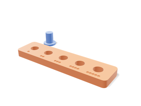 Tolerance testerA ladder of holes from 0.1 to 0.5 mm total gap, with pegs to try in each.71 × 35 × 10 mm · 5 g · 21 min
- Print the tolerance ladder in the filament you’ll use for the real part, at the same speed and temperature.
- Try the peg in each hole. The smallest hole it enters with a firm push is your press fit. The first one it turns freely in is your sliding fit.
- Write the numbers on the spool, or in a note next to the printer: “PLA, A1: press 0.1, slide 0.3.”
- Use them in your models, or tell Loftsmith (“sliding fit = 0.3 mm”) and it designs with your values instead of its defaults.
The default ladder uses about 5 g of PLA. Compare that with reprinting a 90 g box because the lid won’t close. Print the test.
Questions people ask
What tolerance should I use for a press fit in 3D printing?
Start with about 0.1 mm of total clearance (0.05 mm per side) on a tuned printer with a 0.4 mm nozzle, then confirm it with a test print. Some printers need 0.0 mm, others 0.2 mm; that spread is why a ten-minute test beats any table.
Is 0.2 mm a good default clearance?
It is a reasonable snug fit on a well-tuned printer, but not a universal answer. Printers differ by 0.1–0.3 mm, and whether 0.2 mm means per side or total changes the result by a factor of two. Say which one you mean, and test it.
Why are my 3D printed holes smaller than designed?
Round holes are exported as polygons that sit inside the true circle, the nozzle pushes the inner wall of a hole slightly inward, and the first layers squash outward into the hole. Together that usually takes 0.1–0.2 mm off a small hole.
Should I scale the model to make parts fit?
No. Scaling changes every dimension in proportion, so the peg grows along with the hole and a gap that was wrong stays wrong. Change the gap in CAD, or use the slicer’s hole compensation setting.
Does PETG need more clearance than PLA?
Often a little, because PETG tends to bulge and string more than PLA. Treat each filament as its own test: the same printer can need different gaps for PLA, PETG and TPU.
Sources and method
The numbers come from Loftsmith’s CAD engine, which uses them to design and check every part it builds, and from the manufacturer and reference sources below. Every figure is checked against those sources and the engine’s own geometry. Found a mistake? Email [email protected] and we’ll fix it.