Servo parallel gripper for a robot arm
A small robot-arm gripper that runs on one MG90S servo. The servo turns a 20-tooth gear, which turns an identical gear the other way, so both jaws open and close together. Each finger hangs on two links of the same length (a parallelogram), so the pads stay square to each other through the whole stroke instead of swinging in an arc. In the Grip animation the gears roll in mesh and the fingers open, close on the object and open again. The checks show the teeth mesh at the right spacing, the jaws open to the size you set and close to 8 mm without touching, the servo's 2.0 kg cm gives about 3 N per jaw on a 30 mm cube, and the TPU pads hold a small wooden block with room to spare.
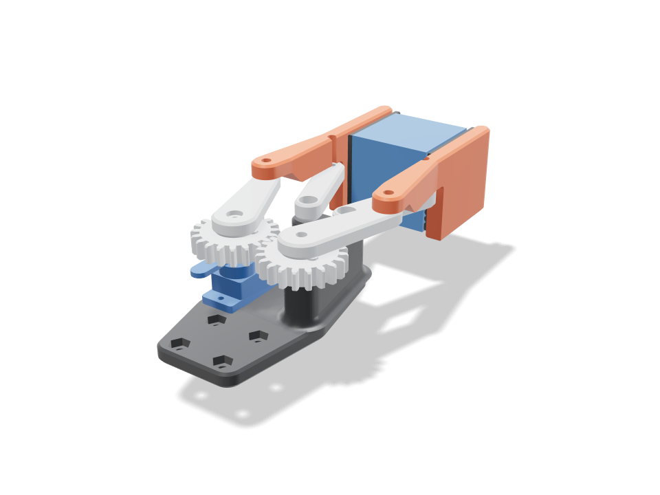
Ask for the sizes you want to tweak, e.g. “make the width adjustable”.
Specs at the default size
Measured from the actual build on a Bambu Lab A1 in pla / TPU. Every number updates live when you drag a slider above.
- Overall size
- 57 × 139 × 38 mm
- Parts
- 11
- Filament
- 38 g
- Print time
- 1 h 52 min
- Build plates
- 1
- Supports
- None needed
Engineering checks
- Gears mesh in phasecentre distance m(z1+z2)/2 = 25.00 mm, 20/20 teeth, module 1.25; overlap 0.000 / 0.000 mm3 at rest / turned 17 deg; contact ratio 1.45; backlash 0.21 mm at the pitch circle (0.1 mm flank gap each side)
- No tooth undercut20 teeth at 1:1 (20 deg) vs 13 minimum
- Teeth take the servo's stall torque3.2 MPa at the tooth root (Lewis, Y 0.322) for half of 0.196 N m through the mesh; PLA allows 16.7 (teeth printed flat, along the layers)
- Jaws stay parallel (four-bar closes)frame pivots and finger pins both 31.4 mm apart, arm and idler both 31.7 mm: a parallelogram, so the finger only translates; idler end meets the finger pin within 0.0e+0 mm at 0/20/30/55 deg
- Jaw rangeopens to 60 mm at 55 deg, closes to 8 mm at 0 deg with the fingers clear of each other and the frame (overlap 0.00 mm3); 55 deg of servo travel
- Object fits between the open jaws15.0 mm each side round the 30 mm cube when open; the jaws meet it at 20.3 deg
- Pads close square on the objectclosed pads touch the cube at x = +-15 mm (overlap 0.00 mm3), 29 mm of pad along it; links and frame clear; open, nothing touches it (0.00 mm3)
- Grip holds the object3.3 N per jaw at stall (2.0 kg cm through 31.7 mm links at 20 deg); friction 3.3 N vs 0.56 N to hold a 19 g wooden cube at 3 g (a quick lift)
- Pivot pinsM3 screws as pins: finger loads 10.7 N (arm) and 11.4 N (idler); bore pressure 0.76 MPa (keep under ~5 in PLA), screw shear 1.6 MPa
- Arm root bending0.6 MPa at the 14 x 5 mm hub for 0.098 N m vs 16.7 along the layers
- Jaw root bending2.9 MPa at the jaw root (grip x3 for a bump) vs 16.7
- Horn screw drives the gearstall torque on the M2 horn screw 7.5 mm out: 26 N, 3.1 MPa bearing in the gear vs 16.7; the stock horn screw on the spline centres it
- Servo seated and screwedMG90S tabs rest on the plate, 2x M2 self-tappers 27.8 mm apart; body passes a window 0.3 mm clear (overlap 0.00 mm3)
- Pad retaineddovetail 2 mm deep, 1.0 mm undercut each side carries the object's weight; slides in from the tip against a closed back end
- MG90S servo goes in23 poses along its path clear of every part.
- 30 mm cube goes in40 poses along its path clear of every part.
- driver: finger pin goes in20 poses along its path clear of every part.
- driver: arm pin goes in20 poses along its path clear of every part.
- driver: gear-right axle goes in20 poses along its path clear of every part.
Adjustable sizes
| Setting | Default | Range |
|---|---|---|
| Max jaw opening | 60 mm | 40–80 mm |
| Finger length | 36 mm | 24–56 mm |
| Object size | 30 mm | 15–50 mm |
| Held object | cube | — |
| Pivot screws | M3 | — |
Parts list
| Part | Qty | Size (mm) | Filament | Time |
|---|---|---|---|---|
| base | 1 | 42 × 77 × 21 | 11 g | 21 min |
| gear-left | 1 | 27 × 27 × 6 | 2 g | 7 min |
| gear-right | 1 | 27 × 27 × 6 | 2 g | 7 min |
| arm-left | 1 | 23 × 41 × 8 | 2 g | 7 min |
| arm-right | 1 | 23 × 41 × 8 | 2 g | 7 min |
| idler-left | 1 | 20 × 39 × 6 | 1 g | 6 min |
| idler-right | 1 | 20 × 39 × 6 | 1 g | 6 min |
| finger-left | 1 | 11 × 77 × 32 | 6 g | 14 min |
| finger-right | 1 | 11 × 77 × 32 | 6 g | 14 min |
| pad-left | 1 | 4 × 29 × 33 | 3 g | 11 min |
| pad-right | 1 | 4 × 29 × 33 | 3 g | 11 min |
How to make it
- Set Max jaw opening and Object size for the thing you want to pick up, then pick a finger length.
- Print the base, gears, arms and idlers flat in PLA, the fingers top face down, and the two pads in TPU.
- Drop the MG90S into the base and screw its tabs down, screw the horn under the left gear and press it on the spline, then fit gears, arms, idlers and fingers with the pivot screws.
- Slide the pads into the finger grooves from the tip, centre the servo, and mount the base to your arm with the four M3 holes.
Print tips
- Gears and links print flat with 3 walls; check the two gears turn freely together before you fit the arms.
- Print the pads in TPU 95A standing on their back end so the dovetail and ribs come out clean.
- Snug the pivot screws, do not clamp them: the links should swing by their own weight.
FAQ
Will it work with an SG90 instead of an MG90S?
Not as drawn. The SG90 is shorter, so its horn would sit below the gear. The plate, window and gear height are sized for the MG90S, and the grip numbers use its torque.
How heavy an object can it hold?
At stall it squeezes about 3 N per jaw on a 30 mm cube. With TPU pads that holds small light parts like a wooden block or a printed test cube. It is not meant for heavy tools.
Do I need screws?
Yes: M3 screws (or M2.5 / M4 with the slider) act as the pivot pins, two M2 screws hold the servo, and four M3 screws with nuts mount it to an arm.
Need a shape that isn't in the catalog? Describe it in your own words with text to CAD
Comments