ロボットアーム用サーボ式パラレルグリッパー
MG90Sサーボ1個で動く小型のロボットアーム用グリッパーです。サーボが20歯のギアを回し、それが同じギアを逆向きに回すので、両方のジョーがいっしょに開閉します。各フィンガーは同じ長さの2本のリンク(平行四辺形)にぶら下がっているので、弧を描いて振れることなく、ストローク全体でパッドが互いに平行を保ちます。Gripアニメーションでは、ギアが噛み合って回り、フィンガーが開いて対象物をつかみ、また開きます。チェックでは、歯が正しい間隔で噛み合うこと、ジョーが設定した幅まで開き、触れずに8 mmまで閉じること、サーボの2.0 kg cmが30 mmの立方体に対してジョーあたり約3 Nを出すこと、TPUパッドが小さな木のブロックを余裕をもって保持することを確認しています。
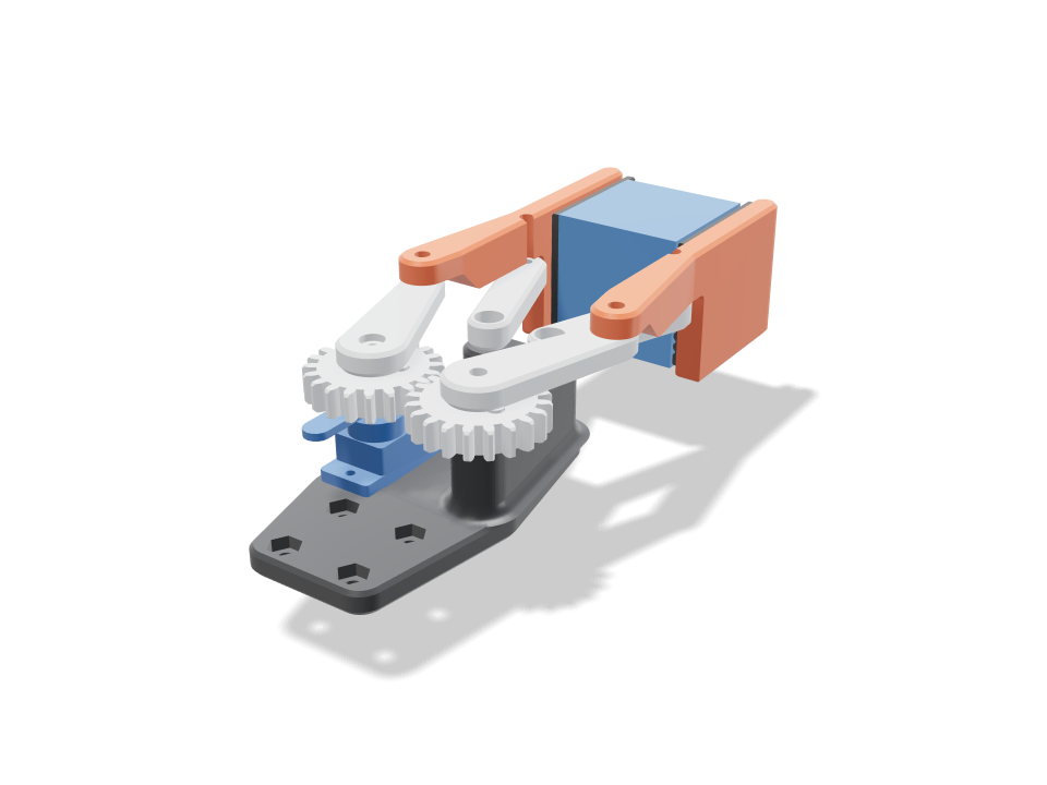
Ask for the sizes you want to tweak, e.g. “make the width adjustable”.
デフォルトサイズでの仕様
Bambu Lab A1でpla / TPUを使った実際のビルドから計測。上のスライダーを動かすと、すべての数値がリアルタイムで更新されます。
- 全体サイズ
- 57 × 139 × 38 mm
- パーツ数
- 11
- フィラメント
- 38 g
- プリント時間
- 1 h 52 min
- プレート数
- 1
- サポート
- 不要
工学チェック
チェック名とパラメーター名はCADエンジンから直接出力されるため、英語で表示されます。
- Gears mesh in phasecentre distance m(z1+z2)/2 = 25.00 mm, 20/20 teeth, module 1.25; overlap 0.000 / 0.000 mm3 at rest / turned 17 deg; contact ratio 1.45; backlash 0.21 mm at the pitch circle (0.1 mm flank gap each side)
- No tooth undercut20 teeth at 1:1 (20 deg) vs 13 minimum
- Teeth take the servo's stall torque3.2 MPa at the tooth root (Lewis, Y 0.322) for half of 0.196 N m through the mesh; PLA allows 16.7 (teeth printed flat, along the layers)
- Jaws stay parallel (four-bar closes)frame pivots and finger pins both 31.4 mm apart, arm and idler both 31.7 mm: a parallelogram, so the finger only translates; idler end meets the finger pin within 0.0e+0 mm at 0/20/30/55 deg
- Jaw rangeopens to 60 mm at 55 deg, closes to 8 mm at 0 deg with the fingers clear of each other and the frame (overlap 0.00 mm3); 55 deg of servo travel
- Object fits between the open jaws15.0 mm each side round the 30 mm cube when open; the jaws meet it at 20.3 deg
- Pads close square on the objectclosed pads touch the cube at x = +-15 mm (overlap 0.00 mm3), 29 mm of pad along it; links and frame clear; open, nothing touches it (0.00 mm3)
- Grip holds the object3.3 N per jaw at stall (2.0 kg cm through 31.7 mm links at 20 deg); friction 3.3 N vs 0.56 N to hold a 19 g wooden cube at 3 g (a quick lift)
- Pivot pinsM3 screws as pins: finger loads 10.7 N (arm) and 11.4 N (idler); bore pressure 0.76 MPa (keep under ~5 in PLA), screw shear 1.6 MPa
- Arm root bending0.6 MPa at the 14 x 5 mm hub for 0.098 N m vs 16.7 along the layers
- Jaw root bending2.9 MPa at the jaw root (grip x3 for a bump) vs 16.7
- Horn screw drives the gearstall torque on the M2 horn screw 7.5 mm out: 26 N, 3.1 MPa bearing in the gear vs 16.7; the stock horn screw on the spline centres it
- Servo seated and screwedMG90S tabs rest on the plate, 2x M2 self-tappers 27.8 mm apart; body passes a window 0.3 mm clear (overlap 0.00 mm3)
- Pad retaineddovetail 2 mm deep, 1.0 mm undercut each side carries the object's weight; slides in from the tip against a closed back end
- MG90S servo goes in23 poses along its path clear of every part.
- 30 mm cube goes in40 poses along its path clear of every part.
- driver: finger pin goes in20 poses along its path clear of every part.
- driver: arm pin goes in20 poses along its path clear of every part.
- driver: gear-right axle goes in20 poses along its path clear of every part.
調整できる寸法
| 設定 | 初期値 | 範囲 |
|---|---|---|
| Max jaw opening | 60 mm | 40–80 mm |
| Finger length | 36 mm | 24–56 mm |
| Object size | 30 mm | 15–50 mm |
| Held object | cube | — |
| Pivot screws | M3 | — |
パーツリスト
| パーツ | 数量 | サイズ(mm) | フィラメント | 時間 |
|---|---|---|---|---|
| base | 1 | 42 × 77 × 21 | 11 g | 21 min |
| gear-left | 1 | 27 × 27 × 6 | 2 g | 7 min |
| gear-right | 1 | 27 × 27 × 6 | 2 g | 7 min |
| arm-left | 1 | 23 × 41 × 8 | 2 g | 7 min |
| arm-right | 1 | 23 × 41 × 8 | 2 g | 7 min |
| idler-left | 1 | 20 × 39 × 6 | 1 g | 6 min |
| idler-right | 1 | 20 × 39 × 6 | 1 g | 6 min |
| finger-left | 1 | 11 × 77 × 32 | 6 g | 14 min |
| finger-right | 1 | 11 × 77 × 32 | 6 g | 14 min |
| pad-left | 1 | 4 × 29 × 33 | 3 g | 11 min |
| pad-right | 1 | 4 × 29 × 33 | 3 g | 11 min |
作り方
- つかみたい物に合わせて最大ジョー開き幅と対象物サイズを設定し、フィンガーの長さを選びます。
- ベース、ギア、アーム、アイドラーはPLAで平置き、フィンガーは上面を下に、2つのパッドはTPUでプリントします。
- MG90Sをベースに入れてタブをネジ留めし、ホーンを左のギアの下にネジ留めしてスプラインに押し込みます。続けてギア、アーム、アイドラー、フィンガーを軸ネジで取り付けます。
- パッドを先端からフィンガーの溝に差し込み、サーボをセンターに合わせ、4つのM3穴でベースをアームに取り付けます。
プリントのコツ
- ギアとリンクは3壁で平置きプリント。アームを付ける前に、2つのギアがいっしょに軽く回ることを確認しましょう。
- パッドはTPU 95Aで後端を下にして立ててプリントすると、ダブテールとリブがきれいに出ます。
- 軸ネジは軽く締める程度にし、締め付けないでください。リンクが自重で振れるくらいが目安です。
よくある質問
MG90Sの代わりにSG90でも動きますか?
このままでは使えません。SG90は背が低いので、ホーンがギアより下に来てしまいます。プレート、窓、ギアの高さはMG90Sに合わせてあり、つかむ力の数値もそのトルクで計算しています。
どのくらいの重さの物をつかめますか?
ストール時に、30 mmの立方体に対してジョーあたり約3 Nで挟みます。TPUパッドなら、木のブロックやプリントしたテストキューブのような小さく軽いパーツを保持できます。重い工具向けではありません。
ネジは必要ですか?
必要です。M3ネジ(スライダーでM2.5 / M4も可)が軸ピンになり、M2ネジ2本でサーボを固定し、M3ネジとナット4組でアームに取り付けます。
カタログにない形が必要ですか? 「テキストからCAD」で、自分の言葉で説明してください
Comments