Pan-Tilt-Kamerahalterung für zwei SG90-Servos
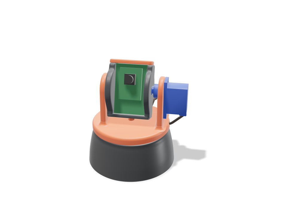
Ein kleiner Pan-Tilt-Kopf wie aus einem Robotik-Bausatz, für eine ESP32-CAM. Der Sockel hält ein SG90 an seinen Laschenschrauben; das Horn dieses Servos sitzt in einer formschlüssigen Tasche unter dem orangefarbenen Joch und dreht es bis zu 90 Grad in jede Richtung. Das Joch trägt das zweite SG90, dessen Horn die Kamerawiege dreht. Auf der anderen Seite sitzt die Wiege auf einem gedruckten Lagerzapfen, sie wird also beidseitig gehalten und kann nicht abrutschen, sobald das Servo eingeschraubt ist. Das Board gleitet in Randnuten hinein, und oben wird eine kleine Kappe aufgeschraubt. Das Kabel des Tilt-Servos rastet in eine Nut rund um das Joch ein, läuft in einer lockeren Schlaufe zum Sockel und rastet in eine Nut an der Rückseite ein, sodass es dem Schwenken folgt, ohne hängen zu bleiben. Der Build prüft, dass beide Servos reichlich Drehmoment für Wiege und Board haben (deutlich unter einem Viertel des Blockiermoments eines SG90), dass beim ganzen Pan- und Tilt-Schwenk nichts irgendwo anstößt, dass das Kabel genug Spiel für volle 90 Grad Pan in jede Richtung hat, dass jedes Teil auf einem echten Weg hineinkommt und dass es ohne Schrauben stabil steht. Gedruckte Passungen, Servospiel und Haltbarkeit brauchen noch einen Testdruck.
Ask for the sizes you want to tweak, e.g. “make the width adjustable”.
Daten bei Standardgröße
Gemessen am echten Build auf einem Bambu Lab A1 in PLA. Jede Zahl aktualisiert sich live, wenn du oben an einem Regler ziehst.
- Gesamtgröße
- 74 × 74 × 89 mm
- Teile
- 4
- Filament
- 59 g
- Druckzeit
- 1 h 45 min
- Druckplatten
- 1
- Stützstrukturen
- Nicht nötig
Technische Prüfungen
Namen von Prüfungen und Parametern kommen direkt aus der CAD-Engine und sind auf Englisch.
- Tilt servo has the torque8.44 N.mm worst case (24.8 g cradle + cap + 10 g board, CG 1.1 mm off the axis at up to 60 deg = 0.26, plus starting a full-speed move with all mass at the 28 mm sweep radius = 8.18) vs SG90 stall 177 N.mm: under a quarter
- Pan servo has the torque15.43 N.mm to start a full-speed pan (66 g turning, I = 368 g.cm2) vs 177 N.mm stall
- Yoke stays on the pan horn1.3 N pull on a horn screw (turning group CG 3.8 mm off the pan axis, bumped x2, levered over 8 mm) vs ~40 N for an M2 self-tapper 2.5 mm into PLA, derated; the horn is also keyed into its recess for torque
- Pivot stub carries a knock0.10 MPa bending at the 6 mm stub root (half the cradle at a 5 g knock, sharp-root factor 2.3) vs 16.7 along the layers; bearing 0.03 MPa vs ~5 MPa for PLA sliding
- Arms take a 5 N knock at the top2.3 MPa at the 4.3 x 28 mm arm root (39 mm tall, bending across the layers) vs 5.0
- Tilt SG90 seats in the arm windowcase 0.2 mm clear in the window, tabs flat on the arm, two M2 tab screws; horn keyed 2.0 mm into the cradle recess; overlap 0.00 mm3
- Pan SG90 hangs on its tabs in the basetabs on the pocket ledge with two M2 screws, horn keyed into the yoke floor; overlap 0.00 mm3
- Cradle is trapped between stub and horncradle can float 0.6 mm toward the stub: the stub stays 3.1 mm in its bore and the horn stays 3.0 mm on the spline; no glue
- Board slides in and is heldPCB edges 0.7 mm deep in 1.9 mm grooves with 45 deg lead-ins, 0.3 mm side play, lifts at most 0.3 mm under the cap; header pins reach through two back windows; overlap 0.00 mm3
- Tilt sweep is clearcradle, cap and board sampled every 10 deg: clear to +/-180 deg (no contact at all; the SG90's own +/-90 deg is the limit); set range +/-60
- Pan sweep is clearyoke, tilt servo and cradle sampled at +/-45 and +/-90 deg against the base: overlap 0.00 mm3; 0.8 mm seam under the yoke
- Leads route clear, exit low at the backpan lead in the drop-in slot under the base; tilt lead snaps into a groove round the yoke rim, crosses in a service loop and snaps into a groove down the back of the base; both leave at the back within 6 mm of the desk; tightest bend 7.0 mm (>= 6 mm, 5x the 1.2 mm ribbon it bends across); overlap 0.00 mm3
- Tilt lead has slack for the whole pan96 mm free loop vs 91 mm needed at 90 deg (worst of +/-90): wrapped round the base at 36 mm radius, plus the drop and 15 mm spare
- Tilt lead is long enough240 mm from the servo to 25 mm past the back exit (12 mm behind the base) vs the 250 mm SG90 lead
- Stands steady without screws or tapetips only past 53 deg (203 g, CG 27 mm up, 1.3 mm off centre, 74 mm foot)
- pan SG90 + horn goes in23 poses along its path clear of every part.
- tilt SG90 + horn goes in16 poses along its path clear of every part.
- ESP32-CAM board goes in26 poses along its path clear of every part.
- OV2640 camera + lens goes in26 poses along its path clear of every part.
- driver: tilt tab screws goes in20 poses along its path clear of every part.
- driver: cap screws goes in20 poses along its path clear of every part.
Anpassbare Maße
| Einstellung | Standard | Bereich |
|---|---|---|
| Camera board width | 27 mm | 24–32 mm |
| Camera board height | 40.5 mm | 36–48 mm |
| Tilt range (each way) | 60 deg | 20–90 deg |
| Pan range (each way) | 90 deg | 30–90 deg |
| Base mounting | screws | — |
Teileliste
| Teil | Anz. | Größe (mm) | Filament | Zeit |
|---|---|---|---|---|
| base | 1 | 74 × 74 × 31 | 35 g | 52 min |
| yoke | 1 | 66 × 65 × 46 | 15 g | 28 min |
| cradle | 1 | 35 × 32 × 44 | 9 g | 19 min |
| top-cap | 1 | 35 × 11 × 3 | 1 g | 6 min |
So wird’s gemacht
- Stell Breite und Höhe des Kamera-Boards ein, falls deins nicht die Standard-ESP32-CAM mit 27 × 40,5 mm ist, und wähl dann, wie weit sie schwenken und neigen soll.
- Wähl Schrauben oder doppelseitiges Klebeband für den Sockel und druck die vier Teile in PLA ohne Stützen.
- Setz das Pan-Servo in den Sockel und schraub seine Laschen fest, dann schraub sein Horn in die Tasche des Jochs und drück das Joch auf das Servo.
- Schraub das Tilt-Horn in die Wiege, schieb die Wiege auf den Lagerzapfen, drück das Tilt-Servo von außen hinein, drück sein Kabel in die Nuten am Rand und am Sockel, dann schieb das Board hinein und schraub die Kappe auf.
Drucktipps
- Jedes Teil wird so gedruckt, wie es sitzt, auf einer flachen Seite ohne Stützen: etwa 60 g und unter 2 Stunden bei 2 Wänden und 15 % Infill.
- Nimm 3 Wände für Joch und Wiege, damit die kleinen selbstschneidenden M2-Schrauben genug Kunststoff zum Greifen haben.
- Wenn die Wiege auf dem Lagerzapfen schwergängig ist, hilft leichtes Anschleifen des Zapfens oder ein Tropfen trockenes PTFE-Schmiermittel.
Häufige Fragen
Funktioniert es mit einer kleinen USB-Webcam statt einer ESP32-CAM?
Ja, wenn die Platine der Webcam in die Nuten gleitet. Stell die Regler für Board-Breite und -Höhe auf deine Platine ein und prüf, dass ihre Dicke nahe an 1,6 mm liegt.
Kann die Kamera weiter als 90 Grad neigen?
Die Wiege selbst kommt ganz herum frei, die Grenze ist also das SG90, das sich etwa 90 Grad in jede Richtung dreht. Der Tilt-Regler geht bis dorthin.
Wo laufen die Servokabel?
Das Pan-Kabel liegt in einem Schlitz unter dem Sockel. Das Tilt-Kabel wird in eine Nut am Rand des Jochs gedrückt, hängt hinten in einer kurzen Schlaufe und wird in eine Nut an der Rückseite des Sockels gedrückt, sodass beide zusammen hinten herauskommen. Die Schlaufe hat genug Spiel für den vollen Pan-Schwenk.
Du brauchst eine Form, die nicht im Katalog ist? Beschreib sie in deinen eigenen Worten mit Text zu CAD
Comments