SG90 서보 두 개용 팬틸트 카메라 마운트
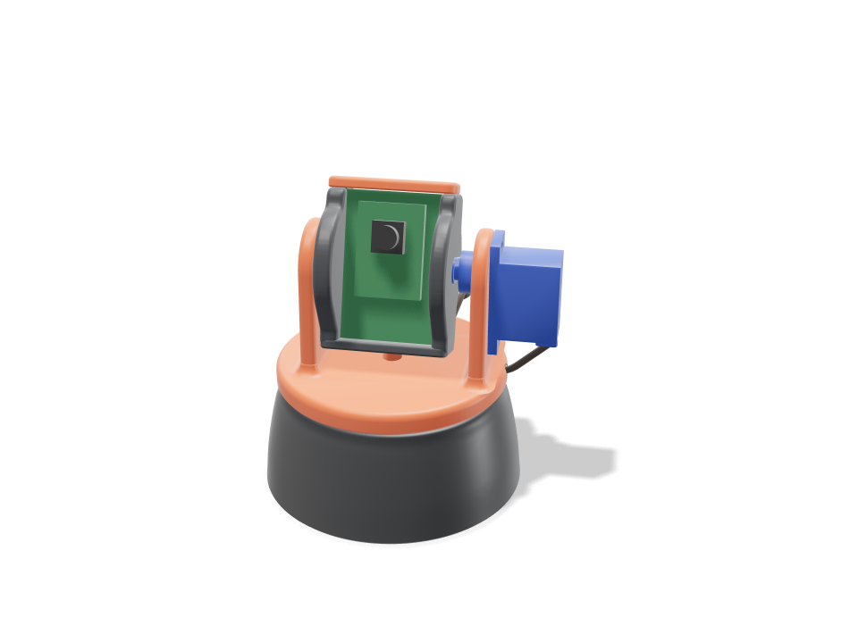
ESP32-CAM용 소형 로봇 키트 스타일 팬틸트 헤드예요. 베이스가 첫 번째 SG90을 탭 나사로 잡고, 그 서보의 혼이 주황색 요크 아래 키 홈 포켓에 들어가 요크를 양쪽으로 최대 90도씩 돌려요. 요크에는 두 번째 SG90이 실리고, 그 혼이 카메라 크래들을 돌려요. 반대쪽에서는 크래들이 출력된 피벗 스터브 위에 얹혀 양쪽에서 지지되기 때문에, 서보를 나사로 고정하면 빠지지 않아요. 보드는 가장자리 홈을 따라 밀어 넣고 작은 캡을 위에 나사로 고정해요. 틸트 서보의 선은 요크를 두르는 홈에 끼우고, 느슨한 고리로 베이스까지 건너가 뒤쪽 홈에 끼우기 때문에 팬을 따라 걸리지 않고 움직여요. 빌드에서는 두 서보 모두 크래들과 보드를 움직일 토크가 충분한지(SG90 스톨 토크의 4분의 1보다 한참 아래), 팬과 틸트 전체 범위에서 아무것도 부딪히지 않는지, 선에 양쪽 90도 팬을 다 할 만큼 여유가 있는지, 각 부품이 실제 경로로 들어가는지, 나사 없이도 안정적으로 서는지 검사해요. 출력된 끼워 맞춤, 서보 유격, 내구성은 여전히 테스트 출력으로 확인해야 해요.
Ask for the sizes you want to tweak, e.g. “make the width adjustable”.
기본 크기 사양
Bambu Lab A1에서 PLA로 실제 빌드해 측정했어요. 위 슬라이더를 움직이면 모든 숫자가 실시간으로 바뀌어요.
- 전체 크기
- 74 × 74 × 89 mm
- 부품 수
- 4
- 필라멘트
- 59 g
- 출력 시간
- 1 h 45 min
- 빌드 플레이트
- 1
- 서포트
- 필요 없음
공학 검사
검사 이름과 파라미터 이름은 CAD 엔진에서 그대로 나오기 때문에 영어로 표시돼요.
- Tilt servo has the torque8.44 N.mm worst case (24.8 g cradle + cap + 10 g board, CG 1.1 mm off the axis at up to 60 deg = 0.26, plus starting a full-speed move with all mass at the 28 mm sweep radius = 8.18) vs SG90 stall 177 N.mm: under a quarter
- Pan servo has the torque15.43 N.mm to start a full-speed pan (66 g turning, I = 368 g.cm2) vs 177 N.mm stall
- Yoke stays on the pan horn1.3 N pull on a horn screw (turning group CG 3.8 mm off the pan axis, bumped x2, levered over 8 mm) vs ~40 N for an M2 self-tapper 2.5 mm into PLA, derated; the horn is also keyed into its recess for torque
- Pivot stub carries a knock0.10 MPa bending at the 6 mm stub root (half the cradle at a 5 g knock, sharp-root factor 2.3) vs 16.7 along the layers; bearing 0.03 MPa vs ~5 MPa for PLA sliding
- Arms take a 5 N knock at the top2.3 MPa at the 4.3 x 28 mm arm root (39 mm tall, bending across the layers) vs 5.0
- Tilt SG90 seats in the arm windowcase 0.2 mm clear in the window, tabs flat on the arm, two M2 tab screws; horn keyed 2.0 mm into the cradle recess; overlap 0.00 mm3
- Pan SG90 hangs on its tabs in the basetabs on the pocket ledge with two M2 screws, horn keyed into the yoke floor; overlap 0.00 mm3
- Cradle is trapped between stub and horncradle can float 0.6 mm toward the stub: the stub stays 3.1 mm in its bore and the horn stays 3.0 mm on the spline; no glue
- Board slides in and is heldPCB edges 0.7 mm deep in 1.9 mm grooves with 45 deg lead-ins, 0.3 mm side play, lifts at most 0.3 mm under the cap; header pins reach through two back windows; overlap 0.00 mm3
- Tilt sweep is clearcradle, cap and board sampled every 10 deg: clear to +/-180 deg (no contact at all; the SG90's own +/-90 deg is the limit); set range +/-60
- Pan sweep is clearyoke, tilt servo and cradle sampled at +/-45 and +/-90 deg against the base: overlap 0.00 mm3; 0.8 mm seam under the yoke
- Leads route clear, exit low at the backpan lead in the drop-in slot under the base; tilt lead snaps into a groove round the yoke rim, crosses in a service loop and snaps into a groove down the back of the base; both leave at the back within 6 mm of the desk; tightest bend 7.0 mm (>= 6 mm, 5x the 1.2 mm ribbon it bends across); overlap 0.00 mm3
- Tilt lead has slack for the whole pan96 mm free loop vs 91 mm needed at 90 deg (worst of +/-90): wrapped round the base at 36 mm radius, plus the drop and 15 mm spare
- Tilt lead is long enough240 mm from the servo to 25 mm past the back exit (12 mm behind the base) vs the 250 mm SG90 lead
- Stands steady without screws or tapetips only past 53 deg (203 g, CG 27 mm up, 1.3 mm off centre, 74 mm foot)
- pan SG90 + horn goes in23 poses along its path clear of every part.
- tilt SG90 + horn goes in16 poses along its path clear of every part.
- ESP32-CAM board goes in26 poses along its path clear of every part.
- OV2640 camera + lens goes in26 poses along its path clear of every part.
- driver: tilt tab screws goes in20 poses along its path clear of every part.
- driver: cap screws goes in20 poses along its path clear of every part.
조절 가능한 치수
| 설정 | 기본값 | 범위 |
|---|---|---|
| Camera board width | 27 mm | 24–32 mm |
| Camera board height | 40.5 mm | 36–48 mm |
| Tilt range (each way) | 60 deg | 20–90 deg |
| Pan range (each way) | 90 deg | 30–90 deg |
| Base mounting | screws | — |
부품 목록
| 부품 | 수량 | 크기(mm) | 필라멘트 | 시간 |
|---|---|---|---|---|
| base | 1 | 74 × 74 × 31 | 35 g | 52 min |
| yoke | 1 | 66 × 65 × 46 | 15 g | 28 min |
| cradle | 1 | 35 × 32 × 44 | 9 g | 19 min |
| top-cap | 1 | 35 × 11 × 3 | 1 g | 6 min |
만드는 법
- 표준 27 x 40.5mm ESP32-CAM이 아니라면 카메라 보드 너비와 높이를 설정하고, 팬과 틸트 범위를 고르세요.
- 베이스 고정 방식을 나사와 양면테이프 중에서 고르고, 네 개의 부품을 PLA로 서포트 없이 출력하세요.
- 팬 서보를 베이스에 넣고 탭을 나사로 고정한 다음, 혼을 요크 포켓에 나사로 고정하고 요크를 서보에 눌러 끼우세요.
- 틸트 혼을 크래들에 나사로 고정하고, 크래들을 피벗 스터브에 끼운 뒤, 틸트 서보를 바깥쪽에서 밀어 넣으세요. 선을 테두리와 베이스 홈에 눌러 끼우고, 보드를 밀어 넣은 다음 캡을 나사로 고정하세요.
출력 팁
- 모든 부품은 놓이는 방향 그대로, 평평한 면을 아래로 서포트 없이 출력돼요. 벽 2개, 인필 15%로 약 60g, 2시간 이내예요.
- 요크와 크래들은 벽 3개로 출력해서 작은 M2 셀프 태핑 나사가 물릴 플라스틱을 넉넉히 확보하세요.
- 크래들이 피벗 스터브에서 뻑뻑하면 스터브를 살짝 사포질하거나 건식 PTFE 윤활제를 한 방울 떨어뜨리면 부드러워져요.
자주 묻는 질문
ESP32-CAM 대신 작은 USB 웹캠도 되나요?
웹캠 회로 기판이 홈에 들어가면 돼요. 보드 너비와 높이 슬라이더를 기판에 맞추고, 두께가 1.6mm에 가까운지 확인하세요.
카메라를 90도보다 더 기울일 수 있나요?
크래들 자체는 한 바퀴 내내 걸리지 않으니, 한계는 SG90이에요. SG90은 양쪽으로 약 90도씩 돌아요. 틸트 슬라이더는 거기까지 올라가요.
서보 케이블은 어디로 지나가나요?
팬 선은 베이스 아래 슬롯에 들어가요. 틸트 선은 요크 테두리를 두르는 홈에 눌러 끼우고, 뒤쪽에 짧은 고리로 늘어졌다가 베이스 뒷면 홈에 눌러 끼우기 때문에 두 선 모두 뒤쪽으로 함께 나와요. 고리에는 전체 팬에 충분한 여유가 있어요.
카탈로그에 없는 모양이 필요하세요? 텍스트 CAD 변환으로 직접 말로 설명해 보세요
Comments