两个 SG90 舵机的云台相机支架
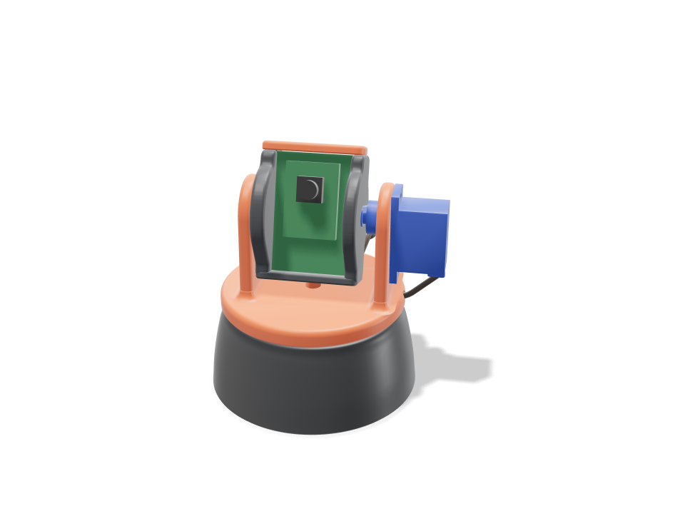
一个机器人套件风格的小型 ESP32-CAM 云台。底座用耳片螺丝固定第一个 SG90,这个舵机的舵盘嵌在橙色叉架下方的键槽里,带动叉架左右各转最多 90 度。叉架上装第二个 SG90,它的舵盘带动相机托架。托架另一侧架在打印出来的转轴短柱上,两侧都有支撑,舵机拧好螺丝后就不会滑脱。板子沿边槽滑入,顶部拧上一个小盖。俯仰舵机的线卡进绕叉架一圈的槽里,以一个松弛的线圈过渡到底座,再卡进背面的槽,所以跟着水平转动也不会被挂住。构建会校验:两个舵机驱动托架和板子的扭矩都很充足(远低于 SG90 堵转扭矩的四分之一),整个水平和俯仰范围内没有任何碰撞,线的余量足够左右各转满 90 度,每个零件都有真实的装入路径,不用螺丝也能稳稳立住。打印出来的配合、舵机虚位和耐用度仍需试打验证。
Building the model
Loading the 3D view
No adjustable sizes
Ask for the sizes you want to tweak, e.g. “make the width adjustable”.
默认尺寸下的规格
在 Bambu Lab A1 上用 PLA 实际构建测得。拖动上方滑块时,每个数字都会实时更新。
- 整体尺寸
- 74 × 74 × 89 mm
- 零件数
- 4
- 耗材
- 59 g
- 打印时间
- 1 h 45 min
- 打印盘
- 1
- 支撑
- 不需要
工程校验
校验和参数名称直接来自 CAD 引擎,以英文显示。
- Tilt servo has the torque8.44 N.mm worst case (24.8 g cradle + cap + 10 g board, CG 1.1 mm off the axis at up to 60 deg = 0.26, plus starting a full-speed move with all mass at the 28 mm sweep radius = 8.18) vs SG90 stall 177 N.mm: under a quarter
- Pan servo has the torque15.43 N.mm to start a full-speed pan (66 g turning, I = 368 g.cm2) vs 177 N.mm stall
- Yoke stays on the pan horn1.3 N pull on a horn screw (turning group CG 3.8 mm off the pan axis, bumped x2, levered over 8 mm) vs ~40 N for an M2 self-tapper 2.5 mm into PLA, derated; the horn is also keyed into its recess for torque
- Pivot stub carries a knock0.10 MPa bending at the 6 mm stub root (half the cradle at a 5 g knock, sharp-root factor 2.3) vs 16.7 along the layers; bearing 0.03 MPa vs ~5 MPa for PLA sliding
- Arms take a 5 N knock at the top2.3 MPa at the 4.3 x 28 mm arm root (39 mm tall, bending across the layers) vs 5.0
- Tilt SG90 seats in the arm windowcase 0.2 mm clear in the window, tabs flat on the arm, two M2 tab screws; horn keyed 2.0 mm into the cradle recess; overlap 0.00 mm3
- Pan SG90 hangs on its tabs in the basetabs on the pocket ledge with two M2 screws, horn keyed into the yoke floor; overlap 0.00 mm3
- Cradle is trapped between stub and horncradle can float 0.6 mm toward the stub: the stub stays 3.1 mm in its bore and the horn stays 3.0 mm on the spline; no glue
- Board slides in and is heldPCB edges 0.7 mm deep in 1.9 mm grooves with 45 deg lead-ins, 0.3 mm side play, lifts at most 0.3 mm under the cap; header pins reach through two back windows; overlap 0.00 mm3
- Tilt sweep is clearcradle, cap and board sampled every 10 deg: clear to +/-180 deg (no contact at all; the SG90's own +/-90 deg is the limit); set range +/-60
- Pan sweep is clearyoke, tilt servo and cradle sampled at +/-45 and +/-90 deg against the base: overlap 0.00 mm3; 0.8 mm seam under the yoke
- Leads route clear, exit low at the backpan lead in the drop-in slot under the base; tilt lead snaps into a groove round the yoke rim, crosses in a service loop and snaps into a groove down the back of the base; both leave at the back within 6 mm of the desk; tightest bend 7.0 mm (>= 6 mm, 5x the 1.2 mm ribbon it bends across); overlap 0.00 mm3
- Tilt lead has slack for the whole pan96 mm free loop vs 91 mm needed at 90 deg (worst of +/-90): wrapped round the base at 36 mm radius, plus the drop and 15 mm spare
- Tilt lead is long enough240 mm from the servo to 25 mm past the back exit (12 mm behind the base) vs the 250 mm SG90 lead
- Stands steady without screws or tapetips only past 53 deg (203 g, CG 27 mm up, 1.3 mm off centre, 74 mm foot)
- pan SG90 + horn goes in23 poses along its path clear of every part.
- tilt SG90 + horn goes in16 poses along its path clear of every part.
- ESP32-CAM board goes in26 poses along its path clear of every part.
- OV2640 camera + lens goes in26 poses along its path clear of every part.
- driver: tilt tab screws goes in20 poses along its path clear of every part.
- driver: cap screws goes in20 poses along its path clear of every part.
可调尺寸
| 设置 | 默认 | 范围 |
|---|---|---|
| Camera board width | 27 mm | 24–32 mm |
| Camera board height | 40.5 mm | 36–48 mm |
| Tilt range (each way) | 60 deg | 20–90 deg |
| Pan range (each way) | 90 deg | 30–90 deg |
| Base mounting | screws | — |
零件清单
| 零件 | 数量 | 尺寸(mm) | 耗材 | 时间 |
|---|---|---|---|---|
| base | 1 | 74 × 74 × 31 | 35 g | 52 min |
| yoke | 1 | 66 × 65 × 46 | 15 g | 28 min |
| cradle | 1 | 35 × 32 × 44 | 9 g | 19 min |
| top-cap | 1 | 35 × 11 × 3 | 1 g | 6 min |
制作方法
- 如果你的不是标准 27 x 40.5 mm 的 ESP32-CAM,就设置相机板的宽和高,再选水平和俯仰的转动范围。
- 底座固定方式选螺丝或双面胶,四个零件用 PLA 打印,无需支撑。
- 把水平舵机放进底座,拧紧耳片螺丝,再把它的舵盘拧进叉架的凹槽,然后把叉架压到舵机上。
- 把俯仰舵盘拧到托架上,把托架套到转轴短柱上,从外侧推入俯仰舵机,把线压进边缘和底座的槽里,然后滑入板子、拧上盖子。
打印建议
- 每个零件都按摆放方向、平面朝下打印,无需支撑:2 层壁、15% 填充约 60 g,不到 2 小时。
- 叉架和托架用 3 层壁,让小号 M2 自攻螺丝有足够的塑料可咬。
- 如果托架在转轴短柱上发涩,把短柱轻轻打磨一下或滴一滴干性 PTFE 润滑剂就顺了。
常见问题
能用小型 USB 摄像头代替 ESP32-CAM 吗?
可以,只要摄像头的电路板能滑进槽里。把板宽和板高滑块设成你的板子尺寸,并确认厚度接近 1.6 mm。
相机能俯仰超过 90 度吗?
托架本身整圈都不会碰撞,所以限制在 SG90,它左右各能转约 90 度。俯仰滑块最大就到这个值。
舵机线怎么走?
水平舵机的线放在底座下方的槽里。俯仰舵机的线压进绕叉架边缘的槽,在背后垂成一个短线圈,再压进底座背面的槽,所以两根线都从背面一起出来。线圈的余量足够完整的水平转动。
需要目录里没有的形状? 用文字生成 CAD,用你自己的话描述它
Comments