SG90サーボ2個で動かすパンチルトカメラマウント
ESP32-CAM用の、ロボットキットのような小型パンチルトヘッドです。ベースは1個目のSG90をタブのネジで固定し、そのサーボのホーンがオレンジのヨーク下のキー付きポケットに収まって、ヨークを左右それぞれ最大90度回します。ヨークには2個目のSG90が載り、そのホーンがカメラのクレードルを回します。反対側ではクレードルがプリントされた軸スタブに載るので両側で支えられ、サーボをネジ留めすれば外れません。ボードは縁の溝に沿って差し込み、小さなキャップを上からネジ留めします。チルトサーボのリード線はヨークを回る溝にはめ込み、ゆるいループでベースへ渡して背面の溝にはめるので、パンに合わせて引っかからずに動きます。ビルドでは、両サーボがクレードルとボードに対してトルクが十分あること(SG90のストールトルクの4分の1を大きく下回る)、パンとチルトの全範囲で何も干渉しないこと、リード線に左右それぞれ90度のパンに足りるたるみがあること、各パーツが実際の経路で組み込めること、ネジなしでも安定して立つことをチェックしています。プリントしたはめあい、サーボのガタ、耐久性はテストプリントで確かめる必要があります。
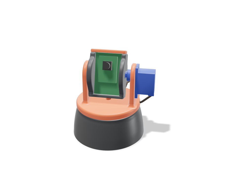
Ask for the sizes you want to tweak, e.g. “make the width adjustable”.
デフォルトサイズでの仕様
Bambu Lab A1でPLAを使った実際のビルドから計測。上のスライダーを動かすと、すべての数値がリアルタイムで更新されます。
- 全体サイズ
- 74 × 74 × 89 mm
- パーツ数
- 4
- フィラメント
- 59 g
- プリント時間
- 1 h 45 min
- プレート数
- 1
- サポート
- 不要
工学チェック
チェック名とパラメーター名はCADエンジンから直接出力されるため、英語で表示されます。
- Tilt servo has the torque8.44 N.mm worst case (24.8 g cradle + cap + 10 g board, CG 1.1 mm off the axis at up to 60 deg = 0.26, plus starting a full-speed move with all mass at the 28 mm sweep radius = 8.18) vs SG90 stall 177 N.mm: under a quarter
- Pan servo has the torque15.43 N.mm to start a full-speed pan (66 g turning, I = 368 g.cm2) vs 177 N.mm stall
- Yoke stays on the pan horn1.3 N pull on a horn screw (turning group CG 3.8 mm off the pan axis, bumped x2, levered over 8 mm) vs ~40 N for an M2 self-tapper 2.5 mm into PLA, derated; the horn is also keyed into its recess for torque
- Pivot stub carries a knock0.10 MPa bending at the 6 mm stub root (half the cradle at a 5 g knock, sharp-root factor 2.3) vs 16.7 along the layers; bearing 0.03 MPa vs ~5 MPa for PLA sliding
- Arms take a 5 N knock at the top2.3 MPa at the 4.3 x 28 mm arm root (39 mm tall, bending across the layers) vs 5.0
- Tilt SG90 seats in the arm windowcase 0.2 mm clear in the window, tabs flat on the arm, two M2 tab screws; horn keyed 2.0 mm into the cradle recess; overlap 0.00 mm3
- Pan SG90 hangs on its tabs in the basetabs on the pocket ledge with two M2 screws, horn keyed into the yoke floor; overlap 0.00 mm3
- Cradle is trapped between stub and horncradle can float 0.6 mm toward the stub: the stub stays 3.1 mm in its bore and the horn stays 3.0 mm on the spline; no glue
- Board slides in and is heldPCB edges 0.7 mm deep in 1.9 mm grooves with 45 deg lead-ins, 0.3 mm side play, lifts at most 0.3 mm under the cap; header pins reach through two back windows; overlap 0.00 mm3
- Tilt sweep is clearcradle, cap and board sampled every 10 deg: clear to +/-180 deg (no contact at all; the SG90's own +/-90 deg is the limit); set range +/-60
- Pan sweep is clearyoke, tilt servo and cradle sampled at +/-45 and +/-90 deg against the base: overlap 0.00 mm3; 0.8 mm seam under the yoke
- Leads route clear, exit low at the backpan lead in the drop-in slot under the base; tilt lead snaps into a groove round the yoke rim, crosses in a service loop and snaps into a groove down the back of the base; both leave at the back within 6 mm of the desk; tightest bend 7.0 mm (>= 6 mm, 5x the 1.2 mm ribbon it bends across); overlap 0.00 mm3
- Tilt lead has slack for the whole pan96 mm free loop vs 91 mm needed at 90 deg (worst of +/-90): wrapped round the base at 36 mm radius, plus the drop and 15 mm spare
- Tilt lead is long enough240 mm from the servo to 25 mm past the back exit (12 mm behind the base) vs the 250 mm SG90 lead
- Stands steady without screws or tapetips only past 53 deg (203 g, CG 27 mm up, 1.3 mm off centre, 74 mm foot)
- pan SG90 + horn goes in23 poses along its path clear of every part.
- tilt SG90 + horn goes in16 poses along its path clear of every part.
- ESP32-CAM board goes in26 poses along its path clear of every part.
- OV2640 camera + lens goes in26 poses along its path clear of every part.
- driver: tilt tab screws goes in20 poses along its path clear of every part.
- driver: cap screws goes in20 poses along its path clear of every part.
調整できる寸法
| 設定 | 初期値 | 範囲 |
|---|---|---|
| Camera board width | 27 mm | 24–32 mm |
| Camera board height | 40.5 mm | 36–48 mm |
| Tilt range (each way) | 60 deg | 20–90 deg |
| Pan range (each way) | 90 deg | 30–90 deg |
| Base mounting | screws | — |
パーツリスト
| パーツ | 数量 | サイズ(mm) | フィラメント | 時間 |
|---|---|---|---|---|
| base | 1 | 74 × 74 × 31 | 35 g | 52 min |
| yoke | 1 | 66 × 65 × 46 | 15 g | 28 min |
| cradle | 1 | 35 × 32 × 44 | 9 g | 19 min |
| top-cap | 1 | 35 × 11 × 3 | 1 g | 6 min |
作り方
- 標準の27 x 40.5 mmのESP32-CAMでない場合はカメラボードの幅と高さを設定し、パンとチルトの範囲を選びます。
- ベースの固定をネジか両面テープから選び、4つのパーツをPLAでサポートなしでプリントします。
- パンサーボをベースに入れてタブをネジ留めし、ホーンをヨークのポケットにネジ留めしてから、ヨークをサーボに押し込みます。
- チルトホーンをクレードルにネジ留めし、クレードルを軸スタブに差し込み、チルトサーボを外側から押し込みます。リード線を縁とベースの溝にはめ、ボードを差し込んでキャップをネジ留めします。
プリントのコツ
- すべてのパーツは置いたときの向きのまま、平らな面を下にしてサポートなしでプリントできます。2壁・インフィル15%で約60 g、2時間以内です。
- ヨークとクレードルは3壁にして、小さなM2タッピングネジがしっかり食い込むだけの樹脂を確保しましょう。
- クレードルが軸スタブで固く感じたら、スタブを軽くやすりがけするか、ドライPTFE潤滑剤を1滴たらすと動きがよくなります。
よくある質問
ESP32-CAMの代わりに小型のUSBウェブカメラでも使えますか?
ウェブカメラの基板が溝に差し込めるなら使えます。ボードの幅と高さのスライダーを基板に合わせ、厚さが1.6 mmに近いことを確認してください。
カメラは90度以上傾けられますか?
クレードル自体はぐるりと一周干渉しないので、限界はSG90です。SG90は左右それぞれ約90度回ります。チルトのスライダーはそこまで設定できます。
サーボのケーブルはどこを通りますか?
パンのリード線はベース下のスロットに収まります。チルトのリード線はヨークの縁を回る溝にはめ込み、背面で短いループを作って、ベース背面の溝にはめ込むので、2本とも背面からまとめて出ます。ループにはパン全範囲に足りるたるみがあります。
カタログにない形が必要ですか? 「テキストからCAD」で、自分の言葉で説明してください
Comments