NEMA17 유성 기어박스
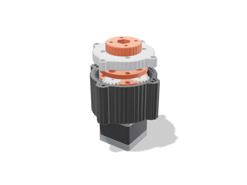
NEMA17 스테퍼에 바로 볼트로 다는 2단 유성 기어박스예요. 1단 선기어는 모터의 D컷 축에 압입되고, 단마다 유성기어 네 개가 홈이 파인 하우징에 새겨진 공용 링기어 안을 돌아요. 1단 캐리어가 2단 선기어를 품고, 2단 캐리어는 캡 안의 608 베어링에 끼운 M8 볼트를 통해 출력 플랜지를 돌려요. 재생하면 축이 선기어를 돌리고, 유성기어가 공전하며 자전하고, 각 캐리어가 실제 감속된 속도로 돌아요. 검사에서는 기어가 정지 상태와 모든 샘플 자세에서 떨어져 있는지, 유성기어가 고르게 배치되고 위상이 맞는지, 이(루이스 치근 응력)와 3mm 강철 핀이 16:1 감속을 거쳐 모터의 스톨 토크 0.4N m(출력 약 5.4N m)를 버티는지, 모든 부품에 들어갈 경로가 있는지 확인해요. 키트예요: 출력 부품에 핀, 베어링, 나사 몇 개가 더해져요.
Ask for the sizes you want to tweak, e.g. “make the width adjustable”.
기본 크기 사양
Bambu Lab A1에서 pla로 실제 빌드해 측정했어요. 위 슬라이더를 움직이면 모든 숫자가 실시간으로 바뀌어요.
- 전체 크기
- 88 × 88 × 67 mm
- 부품 수
- 14
- 필라멘트
- 100 g
- 출력 시간
- 3 h 23 min
- 빌드 플레이트
- 1
- 서포트
- 필요 없음
공학 검사
검사 이름과 파라미터 이름은 CAD 엔진에서 그대로 나오기 때문에 영어로 표시돼요.
- Every part stands free at resttotal overlap 0.000 mm³ between gears, carriers, housing and cap with a 0.15 mm flank gap and 0.4 mm axial gaps
- Planets space evenly(16 + 48) / 4 = 16, a whole number, so all four planets mesh in phase
- Planets clear each other5.8 mm between neighbouring planet tips
- No tooth undercutsun/planet 1.00:1 needs 13+ teeth at 20 deg; smallest here 16
- Teeth overlap in meshcontact ratio 1.35 sun-planet, 1.51 planet-ring after the flank gaps (1.2+ runs smoothly)
- Stage 1 teeth take the stall torque5.0 MPa at the tooth root (Lewis, Y 0.296, 8 mm face) with 0.40 N m on its sun shared by 3 of 4 planets; PLA allows 16.7 along the layers
- Stage 1 planet pins hold27 N per pin: 44 MPa bending in the 3 mm hardened dowel (allow 500), 1.1 MPa in the planet bore (keep under ~6), 11.2 MPa in the 5 mm carrier socket vs 16.7
- Stage 2 teeth take the stall torque13.6 MPa at the tooth root (Lewis, Y 0.296, 10 mm face) with 1.47 N m on its sun shared by 3 of 4 planets; PLA allows 16.7 along the layers
- Stage 2 planet pins hold98 N per pin: 200 MPa bending in the 3 mm hardened dowel (allow 500), 3.3 MPa in the planet bore (keep under ~6), 13.9 MPa in the 10 mm carrier socket vs 16.7
- Sun grips the D-shaft6.9 MPa on 9.7 mm of the shaft flat at 0.4 N m vs 16.7; the bore prints ~0.1 mm small for a press fit
- Motor shaft clears all but its sunshaft tip at 24 mm runs in carrier 1's bushing; overlap 0.00 mm³, sun bore 0.01
- Housing bolts to the motorseats on the 22 mm boss; M3x8 bites 4.5 mm into the motor's threads; 62 N per screw from the 5.4 N m reaction, 5.2 MPa on the floor vs 16.7
- Output bolt carries the torque5.4 N m out: 102 MPa shear in the M8 core (8.8 bolt, allow 190); hex pockets 7.0 / 4.6 MPa vs 16.7
- 608 is seated and capturedflush in a 7 mm pocket on a 3.00 mm lip under the outer race; the inner race is clamped between 8 x 12 mm speed rings by the carrier shoulder and the flange, which runs 1.0 mm clear of the cap; overlap -0.00 mm³
- Cap centres on the housingthe cap sits 1.5 mm deep in the housing's bezel with 0.15 mm all round, so the bearing lands on the ring's axis; flat on the ring top; M3x12 into heat-set inserts in the lobes, 1.2 mm of cap round each screw head
- Ring wall4.2 mm under the flutes, 2.3 mm between each insert and the ring's tooth roots, 3.4 mm bezel rim standing outside the tooth roots
- Bolt and nut fitM8 x 30: the nyloc sits 5.9 mm above the flange underside, its top flush with the bolt end; the carrier shoulder passes the 8 mm lip hole with 0.5 mm all round
- Ratio16.00:1 (2 x 4.00, 16/16/48 teeth, module 1.25): 4.0 motor turns = 0.25 output turns; about 5.4 N m out from 0.4 N m at 92% per stage
- NEMA17 stepper goes in23 poses along its path clear of every part.
- NEMA17 end caps goes in23 poses along its path clear of every part.
- 608 bearing (in the cap) goes in6 poses along its path clear of every part.
- 2x M8 speed ring 8 x 12 x 1 goes in15 poses along its path clear of every part.
- M8 x 30 hex bolt goes in13 poses along its path clear of every part.
- M8 nyloc nut (in the flange) goes in15 poses along its path clear of every part.
- 3 mm steel pins, stage 1 goes in10 poses along its path clear of every part.
- 3 mm steel pins, stage 2 goes in10 poses along its path clear of every part.
- 4x M3x8 into the motor goes in15 poses along its path clear of every part.
- 4x M3x12 cap screws goes in15 poses along its path clear of every part.
- driver: motor screws (through the tool holes) goes in20 poses along its path clear of every part.
- driver: cap screws goes in20 poses along its path clear of every part.
조절 가능한 치수
| 설정 | 기본값 | 범위 |
|---|---|---|
| Tooth size (module) | 1.25 mm | 1.25–1.75 mm |
| Sun teeth | 16 | 14–20 |
| Planet teeth | 16 | 14–22 |
| Stages | 2 | 1–2 |
| Gear gap (each flank) | 0.15 mm | 0.1–0.25 mm |
부품 목록
| 부품 | 수량 | 크기(mm) | 필라멘트 | 시간 |
|---|---|---|---|---|
| housing | 1 | 88 × 88 × 44 | 45 g | 1 h 6 min |
| sun 1 | 1 | 22 × 22 × 13 | 2 g | 8 min |
| planet 1-1 | 1 | 22 × 22 × 8 | 2 g | 7 min |
| planet 1-2 | 1 | 22 × 22 × 8 | 2 g | 7 min |
| planet 1-3 | 1 | 22 × 22 × 8 | 2 g | 7 min |
| planet 1-4 | 1 | 22 × 22 × 8 | 2 g | 7 min |
| planet 2-1 | 1 | 22 × 22 × 10 | 2 g | 8 min |
| planet 2-2 | 1 | 22 × 22 × 10 | 2 g | 8 min |
| planet 2-3 | 1 | 22 × 22 × 10 | 2 g | 8 min |
| planet 2-4 | 1 | 22 × 22 × 10 | 2 g | 8 min |
| carrier 1 | 1 | 52 × 52 × 15 | 8 g | 16 min |
| output carrier | 1 | 52 × 52 × 13 | 8 g | 15 min |
| cap | 1 | 80 × 80 × 10 | 15 g | 24 min |
| output flange | 1 | 38 × 38 × 14 | 7 g | 14 min |
만드는 법
- 이 크기, 선기어와 유성기어 잇수, 1단 또는 2단을 고르세요. 기어비와 출력 토크가 검사에서 갱신돼요.
- 하우징, 캐리어, 유성기어는 평평한 면을 아래로, 선기어는 이를 아래로, 캡과 플랜지는 평평한 면을 아래로 출력하세요. 서포트 없음.
- M3 열압입 인서트를 하우징 돌출부에 넣고, 4x M3x8로 모터에 고정하고, 선기어를 축에 눌러 끼운 다음, 압입한 3mm 핀에 유성기어를 단마다 넣으세요.
- M8 볼트를 출력 캐리어 아래에서 위로 밀어 넣고 스페이서 링을 끼운 뒤, 608을 베젤에 넣은 캡을 덮어 나사로 고정하고, 나일록 너트가 있는 플랜지를 볼트에 돌려 끼우세요.
출력 팁
- 표시된 검사 범위라면 PLA로 충분해요. 꾸준한 부하에서는 PETG나 PA-CF 기어가 더 오래가요. 이가 꽉 차도록 기어는 벽 3~4개로 출력하세요.
- 기어가 걸리면 기어 유격을 0.02mm 올리고, 덜컹거리면 낮추세요. 핀에 건식 PTFE 윤활제를 한 방울 떨어뜨리면 좋아요.
- 핀 검사는 경화된 3mm 다웰 핀(ISO 8734)을 기준으로 해요. 잘라 낸 못이나 무른 봉은 휘어요.
자주 묻는 질문
어떤 하드웨어가 필요한가요?
NEMA17 스테퍼, 3mm 강철 다웰 핀(단마다 4개), 608 베어링 1개, 8 x 12 x 1mm 스페이서 링 2개, M8 육각 볼트와 나일록 너트, 4x M3x8과 4x M3x12 나사, 캡과 출력 플랜지용 M3 열압입 인서트 4 + 4개예요.
실제로 토크가 얼마나 나오나요?
기본 16:1과 0.4N m 모터에서, 출력한 단마다 효율 92%를 가정하면 플랜지에서 약 5.4N m로 추정돼요. 측정이 아니라 계산이니, 무거운 걸 매달기 전에 작업대에서 시험해 보세요.
1단 버전도 만들 수 있나요?
네. 단 수를 1로 하면 같은 플랜지와 베어링으로 더 짧은 4:1 박스가 돼요. 모터가 네 바퀴 돌면 모든 부품이 제자리로 돌아오기 때문에 동작이 깔끔한 루프로 돌아가요.
카탈로그에 없는 모양이 필요하세요? 텍스트 CAD 변환으로 직접 말로 설명해 보세요
Comments