NEMA17 行星减速箱
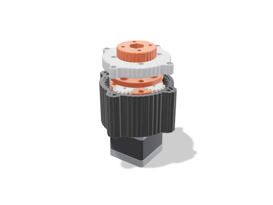
一个直接用螺栓装在 NEMA17 步进电机上的两级行星减速箱。第一级太阳轮压在电机的 D 形轴上,每级四个行星轮绕着刻在凹槽纹外壳里的同一个齿圈转动,第一级行星架带着第二级太阳轮,第二级行星架通过一根穿过端盖里 608 轴承的 M8 螺栓带动输出法兰。按下播放,电机轴带动太阳轮,行星轮公转加自转,每个行星架都按真实的减速后转速转动。校验证明齿轮在静止和每个采样姿态下都互不干涉,行星轮均匀分布且相位正确,轮齿(Lewis 齿根应力)和 3 mm 钢销能经 16:1 减速承受电机 0.4 N m 的堵转扭矩(输出约 5.4 N m),每个零件都有明确的装入路径。这是一套套件:打印件加上销钉、一个轴承和几颗螺丝。
Ask for the sizes you want to tweak, e.g. “make the width adjustable”.
默认尺寸下的规格
在 Bambu Lab A1 上用 pla 实际构建测得。拖动上方滑块时,每个数字都会实时更新。
- 整体尺寸
- 88 × 88 × 67 mm
- 零件数
- 14
- 耗材
- 100 g
- 打印时间
- 3 h 23 min
- 打印盘
- 1
- 支撑
- 不需要
工程校验
校验和参数名称直接来自 CAD 引擎,以英文显示。
- Every part stands free at resttotal overlap 0.000 mm³ between gears, carriers, housing and cap with a 0.15 mm flank gap and 0.4 mm axial gaps
- Planets space evenly(16 + 48) / 4 = 16, a whole number, so all four planets mesh in phase
- Planets clear each other5.8 mm between neighbouring planet tips
- No tooth undercutsun/planet 1.00:1 needs 13+ teeth at 20 deg; smallest here 16
- Teeth overlap in meshcontact ratio 1.35 sun-planet, 1.51 planet-ring after the flank gaps (1.2+ runs smoothly)
- Stage 1 teeth take the stall torque5.0 MPa at the tooth root (Lewis, Y 0.296, 8 mm face) with 0.40 N m on its sun shared by 3 of 4 planets; PLA allows 16.7 along the layers
- Stage 1 planet pins hold27 N per pin: 44 MPa bending in the 3 mm hardened dowel (allow 500), 1.1 MPa in the planet bore (keep under ~6), 11.2 MPa in the 5 mm carrier socket vs 16.7
- Stage 2 teeth take the stall torque13.6 MPa at the tooth root (Lewis, Y 0.296, 10 mm face) with 1.47 N m on its sun shared by 3 of 4 planets; PLA allows 16.7 along the layers
- Stage 2 planet pins hold98 N per pin: 200 MPa bending in the 3 mm hardened dowel (allow 500), 3.3 MPa in the planet bore (keep under ~6), 13.9 MPa in the 10 mm carrier socket vs 16.7
- Sun grips the D-shaft6.9 MPa on 9.7 mm of the shaft flat at 0.4 N m vs 16.7; the bore prints ~0.1 mm small for a press fit
- Motor shaft clears all but its sunshaft tip at 24 mm runs in carrier 1's bushing; overlap 0.00 mm³, sun bore 0.01
- Housing bolts to the motorseats on the 22 mm boss; M3x8 bites 4.5 mm into the motor's threads; 62 N per screw from the 5.4 N m reaction, 5.2 MPa on the floor vs 16.7
- Output bolt carries the torque5.4 N m out: 102 MPa shear in the M8 core (8.8 bolt, allow 190); hex pockets 7.0 / 4.6 MPa vs 16.7
- 608 is seated and capturedflush in a 7 mm pocket on a 3.00 mm lip under the outer race; the inner race is clamped between 8 x 12 mm speed rings by the carrier shoulder and the flange, which runs 1.0 mm clear of the cap; overlap -0.00 mm³
- Cap centres on the housingthe cap sits 1.5 mm deep in the housing's bezel with 0.15 mm all round, so the bearing lands on the ring's axis; flat on the ring top; M3x12 into heat-set inserts in the lobes, 1.2 mm of cap round each screw head
- Ring wall4.2 mm under the flutes, 2.3 mm between each insert and the ring's tooth roots, 3.4 mm bezel rim standing outside the tooth roots
- Bolt and nut fitM8 x 30: the nyloc sits 5.9 mm above the flange underside, its top flush with the bolt end; the carrier shoulder passes the 8 mm lip hole with 0.5 mm all round
- Ratio16.00:1 (2 x 4.00, 16/16/48 teeth, module 1.25): 4.0 motor turns = 0.25 output turns; about 5.4 N m out from 0.4 N m at 92% per stage
- NEMA17 stepper goes in23 poses along its path clear of every part.
- NEMA17 end caps goes in23 poses along its path clear of every part.
- 608 bearing (in the cap) goes in6 poses along its path clear of every part.
- 2x M8 speed ring 8 x 12 x 1 goes in15 poses along its path clear of every part.
- M8 x 30 hex bolt goes in13 poses along its path clear of every part.
- M8 nyloc nut (in the flange) goes in15 poses along its path clear of every part.
- 3 mm steel pins, stage 1 goes in10 poses along its path clear of every part.
- 3 mm steel pins, stage 2 goes in10 poses along its path clear of every part.
- 4x M3x8 into the motor goes in15 poses along its path clear of every part.
- 4x M3x12 cap screws goes in15 poses along its path clear of every part.
- driver: motor screws (through the tool holes) goes in20 poses along its path clear of every part.
- driver: cap screws goes in20 poses along its path clear of every part.
可调尺寸
| 设置 | 默认 | 范围 |
|---|---|---|
| Tooth size (module) | 1.25 mm | 1.25–1.75 mm |
| Sun teeth | 16 | 14–20 |
| Planet teeth | 16 | 14–22 |
| Stages | 2 | 1–2 |
| Gear gap (each flank) | 0.15 mm | 0.1–0.25 mm |
零件清单
| 零件 | 数量 | 尺寸(mm) | 耗材 | 时间 |
|---|---|---|---|---|
| housing | 1 | 88 × 88 × 44 | 45 g | 1 h 6 min |
| sun 1 | 1 | 22 × 22 × 13 | 2 g | 8 min |
| planet 1-1 | 1 | 22 × 22 × 8 | 2 g | 7 min |
| planet 1-2 | 1 | 22 × 22 × 8 | 2 g | 7 min |
| planet 1-3 | 1 | 22 × 22 × 8 | 2 g | 7 min |
| planet 1-4 | 1 | 22 × 22 × 8 | 2 g | 7 min |
| planet 2-1 | 1 | 22 × 22 × 10 | 2 g | 8 min |
| planet 2-2 | 1 | 22 × 22 × 10 | 2 g | 8 min |
| planet 2-3 | 1 | 22 × 22 × 10 | 2 g | 8 min |
| planet 2-4 | 1 | 22 × 22 × 10 | 2 g | 8 min |
| carrier 1 | 1 | 52 × 52 × 15 | 8 g | 16 min |
| output carrier | 1 | 52 × 52 × 13 | 8 g | 15 min |
| cap | 1 | 80 × 80 × 10 | 15 g | 24 min |
| output flange | 1 | 38 × 38 × 14 | 7 g | 14 min |
制作方法
- 选模数、太阳轮和行星轮齿数,以及一级或两级;传动比和输出扭矩会在校验中更新。
- 外壳、行星架和行星轮平面朝下打印,太阳轮齿朝下,端盖和法兰平面朝下。无需支撑。
- 把 M3 热熔螺母压进外壳的凸耳,用 4x M3x8 螺丝装到电机上,把太阳轮压到轴上,然后逐级把行星轮装到压好的 3 mm 销上。
- 把 M8 螺栓从输出行星架下方穿上来,加一个垫圈,盖上装好 608 轴承的端盖并拧紧,再把带尼龙锁紧螺母的法兰拧到螺栓上。
打印建议
- 对于所示的校验,PLA 就够用;在持续负载下 PETG 或 PA-CF 齿轮更耐用。齿轮用 3-4 层壁打印,让轮齿是实心的。
- 齿轮卡滞就把齿轮间隙加大 0.02 mm;有松旷声就减小。在销上滴一滴干性 PTFE 润滑剂会有帮助。
- 销钉校验假定使用淬火 3 mm 定位销(ISO 8734);截短的钉子或软棒会弯。
常见问题
需要哪些五金件?
一台 NEMA17 步进电机、3 mm 钢制定位销(每级四根)、一个 608 轴承、两个 8 x 12 x 1 mm 垫圈、一颗 M8 六角螺栓和尼龙锁紧螺母、4x M3x8 和 4x M3x12 螺丝,以及端盖和输出法兰用的 4 + 4 个 M3 热熔螺母。
实际能输出多大扭矩?
默认 16:1、0.4 N m 电机,按每个打印级 92% 效率估算,法兰处约 5.4 N m。这是计算值,不是实测值,所以挂重物之前先在工作台上测一下。
能做单级版本吗?
可以。把级数设为 1,就得到一个更短的 4:1 减速箱,法兰和轴承不变。由于电机转四圈后每个零件都回到原位,动画会是一个干净的循环。
需要目录里没有的形状? 用文字生成 CAD,用你自己的话描述它
Comments