Overhangs and bridges: designing parts that print without supports
Supports cost filament and time, and they leave scars. Most of them can be designed away before the slicer ever sees the part, with a handful of shapes every experienced designer uses without thinking.
Short answer
Keep downward-facing surfaces at 45° or steeper from horizontal and they print without supports on almost any printer. Short, straight, horizontal spans between two supports (bridges) print cleanly on a tuned printer, typically up to 10–20 mm. Chamfer bottom edges at 45° instead of filleting them, give sideways holes a teardrop or flat top, and choose the print orientation that puts the fewest overhangs facing down.
A printer builds a part the way a bricklayer builds a wall: one course on top of the last. Each new line of plastic needs something under it. Lean the wall out a little and every course overhangs the one below by a fraction of a line, which is fine. Lean it out too far, or ask for a flat ceiling over empty space, and the plastic has nothing to sit on.
That one idea explains every rule in this guide. Design with it in mind and most supports disappear.
The 45° rule
A surface that faces downward prints cleanly as long as it is at least 45° from horizontal. At that angle, each new line sits half on the line below it, which is enough to hold it while it cools.
| Angle | Result on a typical FDM printer |
|---|---|
| 90° (vertical wall) | Perfect |
| 60° | Clean |
| 45° | Clean on almost any printer. The standard design limit |
| 30–40° | Rough underside; fine on some well-cooled printers |
| Below 30° | Droops and curls; needs support or a redesign |
| 0° (flat ceiling) | Only as a short bridge between two supports |
Loftsmith’s print check uses the same 45° line: it measures the area of every face tilted past 45° from vertical and facing down, estimates how much support filament it would take, and suggests chamfers or a different orientation when supports look likely.
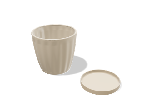 Fluted planter with saucerA fluted planter whose gentle flare and rolled rim print without supports.265 × 125 × 115 mm · 123 g · 3 h 00 min
Bridges
A bridge is the exception to “nothing under it”. When a flat span runs straight between two supports, the printer stretches each line across the gap like a rope, anchoring both ends. Cooled quickly, it holds.
- Keep them short. On a tuned printer, 10–20 mm prints cleanly. Longer bridges sag progressively.
- Keep them straight. Both ends need an anchor. A flat ceiling over a round hole isn’t a bridge, because most of its lines end in mid-air.
- Expect a rough underside. The first bridge layer droops a little. Hide it on the inside, or put the bridge where nobody looks.
If your design depends on a long bridge, print a bridge test first. The limit depends on cooling, speed and filament as much as on the printer.
Chamfer the bottom, fillet the top
This is the single most useful habit in design for printing. A fillet (a rounded edge) starts vertical and ends horizontal. On a top edge that’s fine. On an edge facing the bed, the last part of the curve is a nearly flat overhang, and it droops.
A 45° chamfer on the same edge prints perfectly, because every part of it is at the safe angle. So round the edges on top and on vertical corners, and chamfer the edges that face down. The part looks almost the same and prints far better.
The same trick removes supports from many features. A shelf sticking out of a wall can sit on a 45° gusset. A flat ceiling inside a box can become a shallow roof. A sideways peg can grow a small 45° fin underneath.
Holes on their side
A round hole that runs parallel to the bed has a curved roof, and the top of that curve is flat. It sags, so the hole comes out oval and a screw or pin won’t fit.
Give the hole a teardrop top, a 45° point in place of the arc, or cut a short flat across its top so the printer bridges a short straight line. Both look nearly round and fit what they should. The screw hole guide covers the sizes.
Orientation first
Before changing any geometry, try turning the part. The same shape can need supports under ten faces in one orientation and none in another.
- Put the largest flat face on the bed.
- Face overhangs upward where you can; an overhang on top is just a slope.
- Check what the orientation does to strength: layers are weaker across than along (see the weight guide).
- If no orientation works, split the part into pieces that each print flat. The splitting guide shows how.
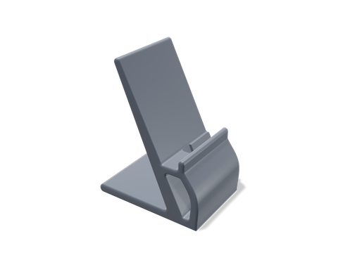 Phone charging standA one-piece charging stand, printed on its side so its window and lead channel need no supports.100 × 70 × 127 mm · 68 g · 1 h 40 min
When supports are the right answer
Some shapes need supports, and that’s fine: an organic figure, a part whose outside must be perfect on all sides, a one-off where redesigning costs more than peeling. When you use them:
- Tree (organic) supports touch the part in fewer places and leave smaller scars than grid supports.
- Use support blockers to keep supports out of holes, hinges and gaps where they can’t be removed.
- Paint supports only where they are needed, instead of supporting everything the slicer flags.
Questions people ask
What overhang angle can a 3D printer print?
45° from horizontal prints on almost any FDM printer. A well-cooled, tuned printer can often manage 50–60°, but the underside gets rougher as the angle gets shallower. Design to 45° and you never need to find out.
How long can a 3D printer bridge?
Short, straight bridges of 10–20 mm print cleanly on most tuned printers. Longer ones sag progressively; the exact limit depends on cooling, speed and material, so print a bridge test if your design depends on a long one.
Should I use fillets or chamfers for 3D printing?
Chamfers on edges that face the bed, because a 45° chamfer prints without support while the bottom of a fillet becomes a flat overhang. Fillets are fine on top edges and vertical edges.
Why are the undersides of my overhangs rough?
Each layer is hanging a little further out over thin air, so it droops before it cools. More part cooling, lower speed and a steeper angle all help. Chamfering or reorienting the part fixes it for good.
Sources and method
The numbers come from Loftsmith’s CAD engine, which uses them to design and check every part it builds, and from the manufacturer and reference sources below. Every figure is checked against those sources and the engine’s own geometry. Found a mistake? Email [email protected] and we’ll fix it.