Loftsmithが1つのプロンプトから設計したRC全翼機
これは誰も図面を描いていません。Loftsmithに渡したのは "A 3D printable RC flying wing"(3Dプリントできる RC全翼機)という一文だけ。寸法も部品もハードウェアも指定しませんでしたが、Loftsmithは機体を7段階で計画し、自力で作り上げました。スパン1 m、後退角37°の推進式全翼機で、Bambu Lab A1ですべてPLAでプリントし、定番の入門キット(2212モーター、30 A ESC、3S 2200 LiPo、MG90Sサーボ2個)に合わせたサイズです。センターポッドは面一のマグネット式ハッチの下にバッテリーを収め、左右それぞれに翼パネルが2枚あります。パネルは翼根面を下にして立ててプリントし、内部ウェブの上に0.8 mmのスキンを張った構造で、8 mmのカーボンスパーと、2°のねじり下げを付けた6 mmジョイナーに通します。エレボンはCAヒンジで±15°動き、内側パネルに平らに寝かせたサーボで駆動します。モーターは後縁の後ろのポッドに収まります。ここにあるのはLoftsmithが作ったものそのままで、手を加えておらず、Loftsmith自身の正直なメモも含みます。サイズの割に重く、重心を合わせるには機首におもりが必要です。私たちが手で仕上げた翼は、RC全翼機ジェネレーターをご覧ください。
Loftsmithが1つのプロンプトから作成
“A 3D printable RC flying wing”
下のプロンプトからLoftsmithが設計したものを、手を加えずそのまま掲載しています。製作を計画し、チェック結果に応じてモデルを書いては作り直し、最後まで自力で仕上げました。
- 設計ターン
- 22
- ビルド(成功 14)
- 19
- トークン(入力 / 出力)
- 3.23M / 0.52M
- Loftsmithクレジット
- 271
- 合格したエンジニアリングチェック
- 68
2026-09-28に設計。Proプランの料金では、271クレジットで約54ドルです。
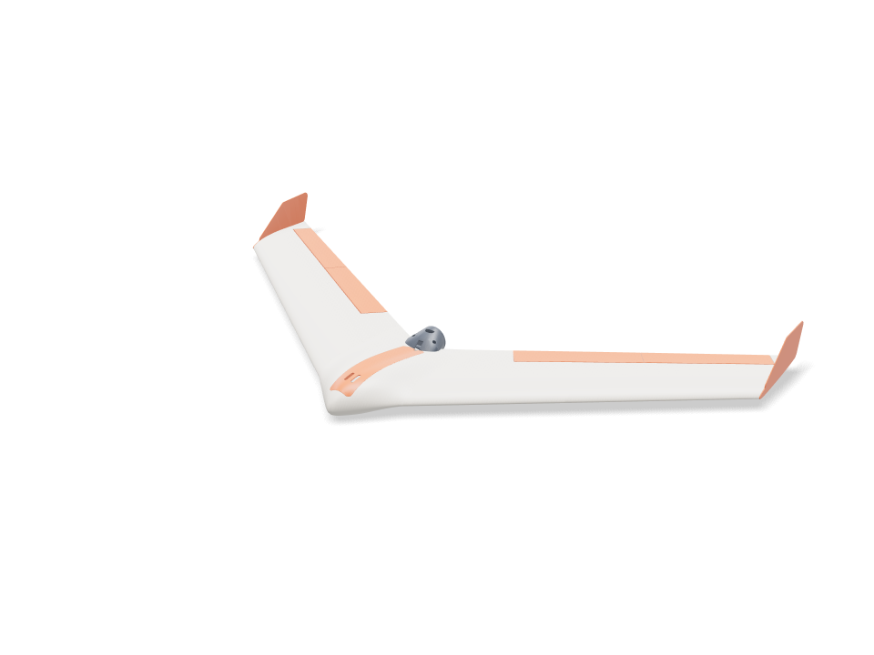
Ask for the sizes you want to tweak, e.g. “make the width adjustable”.
デフォルトサイズでの仕様
Bambu Lab A1でPLAを使った実際のビルドから計測。上のスライダーを動かすと、すべての数値がリアルタイムで更新されます。
- 全体サイズ
- 1003 × 553 × 85 mm
- パーツ数
- 18
- フィラメント
- 677 g
- プリント時間
- 19 h 19 min
- プレート数
- 6
- サポート
- 不要
工学チェック
チェック名とパラメーター名はCADエンジンから直接出力されるため、英語で表示されます。
- Battery reaches the balance pointbalance at 20.0 % MAC = 212 mm behind the root LE needs the battery centre at y 68; the bay slides it 65 to 96 mm
- Nose weight fits the nose tip40 g of lead (26 x 7 x 20 mm) ahead of the battery, overlap 0.0 mm³; room for 57 g
- Nose weight stays modest40 g of lead = 3.7 % of all-up weight (limit 5 %); LW-PLA wing panels are the next way to cut it
- Battery fits the bay, front and backoverlap 0.0 / 0.0 mm³; 31 mm of slide, loads straight down through a 40 mm wide opening
- ESC and receiver fit their side baysoverlap 0.0 / 0.0 mm³; they slide in sideways under the skin, before the battery
- Spar tunnel stays inside the joint face1.6 mm of PLA above and below the 8 mm tube at the panel joint (75 % chord)
- Wing loading1083 g all-up on 18.6 dm² = 58 g/dm²; stall about 11.5 m/s (CL 0.7). Limit 60 g/dm² and a stall under 12 m/s for a firm hand launch; the plan's 35 g/dm² is not reachable with 0.8 mm PLA skins
- Enough thrust to hand launchabout 800 g static thrust (estimate) for 1083 g all-up = 0.74 : 1 (want 0.6+)
- Carbon spar at the panel root (4 g pull-up)80 MPa in an 8x6 mm carbon tube (allow ~250 MPa)
- Joiner at the panel joint (4 g pull-up)57 MPa in a 6x4 mm carbon tube (allow ~250 MPa); the glued PLA joint face shares the load
- Spar and joiner buried in the wing1.2 mm of PLA round the 8 mm spar out to 230 mm (100.0 % inside) and round the 6 mm joiner, 60 mm into each panel (100.0 %)
- Spar and joiner don't clashthe 8 mm spar stops 40 mm short of the panel joint on its own shear web; the joiner rides the 40 % chord web behind it
- Anti-twist pins buried at both joints3 mm carbon pins, 11 mm into each face, bosses 100.0 % inside the skin
- Internal webs print without supportdiagonal webs lean at most 27° from vertical with the panel standing on its root
- Wing inner panel fits the A1 bed190 mm tall standing on its root; 274 x 21 mm footprint needs 209 mm turned 45°
- Wing inner panel stands steady while printingits centre of mass (y 210) sits 59 mm inside the root face (y 60 to 269); print with a 5 mm brim
- Wing outer panel fits the A1 bed230 mm tall standing on its root; 323 x 19 mm footprint needs 242 mm turned 45°
- Wing outer panel stands steady while printingits centre of mass (y 358) sits 28 mm inside the root face (y 203 to 386); print with a 5 mm brim
- Fits the A1 bed standing on its side160 mm tall; 282 x 51 mm footprint needs 236 mm turned 45°
- Centre filament target153 g of PLA (target 170 g)
- Wing panel filament target361 g of PLA for all four panels (target 400 g)
- Elevon sizeabout 3.30 dm² = 18 % of the wing (aim 12-25 %), 28 % of the local chord
- Elevons swing ±15° clear of the wingtightest gap at the hinge face 0.9 mm (V below and Λ above the hinge line at 22°); ends cut square to the hinge with 0.8 mm gaps
- Hinge pockets stay under the skin1.0 mm of top skin over the thinnest end of the strip pockets
- Hinge strip flex0.8 mm bought CA hinge bends over 3.6 mm of free length: 2.9 % surface strain at 15° (keep under ~10 % for long life)
- Elevon halves fit the A1 bed on end201 / 201 mm tall standing on their square ends
- Elevon joint pin buried3 mm carbon pin, 11 mm into each half; boss 100.0 % inside the skin
- Servo fits the wing depthMG90S lying flat: 1.4 mm of top skin over the pocket, 1.1 mm above the cover plate
- Servo pocket clear of spar and joinerpocket walls vs spar / joiner sleeves: 0.00 / 0.00 mm³
- Servo travel for ±15° elevonservo horn hole 12.3 mm from the shaft, control horn hole 15.1 mm below the hinge: ±15° needs ±19° of servo
- Servo torque (estimate)about 4.9 N·cm at 22 m/s full throw (hinge-moment coefficient 0.25 assumed) vs ~18 N·cm MG90S stall; keep under half
- Control horn at servo stall2.3 MPa at the horn root with 15 N on the pushrod (servo stalled), along the layers; allow 16.7
- Control horn swings clear of the wingoverlap at +15 / 0 / -15°: 0.0 / 0.0 / 0.2 mm³
- Pushrod runs clear74 mm pushrod under the skin; 0.00 mm³ overlap with the wing, cover, elevon and horn
- Servo lead channel stays inside the skin11 x 6 mm channel for the 15 x 8 x 4.2 mm plug, 135 mm long: 100.0 % inside with its 0.8 mm walls
- Servo cover sits flushthe flat plate stands up to 0.7 mm proud of the curved skin at its edges
- Servo and cover are fastenedservo: 2 tab screws 6 mm into the cover lugs; cover: 2x M2 into heat-set inserts with 1.6 mm boss wall
- Prop clears the trailing edgeblade tips run 5.0 mm behind the swept trailing edge at 102 mm radius; swept disc overlaps the airframe by 0.0 mm³
- Spar covered where the tail thins100.0 % of a 1.2 mm skin round the 8 mm spar is enclosed across the middle 64 mm, with the pod fitted
- Pod bolts clamp solid PLAthe centre tail is 100 % solid round each M3 bolt, so clamping cannot crush a hollow skin
- Pod carries the motor on a hard landing0.14 MPa across the layers of the 1.2 mm PLA shell at a 10 g landing (motor + prop on a 43 mm arm); allow 5.0
- Prop parked clear on landingwith the ESC brake set the prop stops level; its hub bottom sits 15 mm above the pod belly, which touches down first
- Motor and plate are fastenedmotor: 4x M3x6 through the plate into its 16x19 holes; plate: 3x M3x8 into heat-set inserts, 5.3 mm from the plate edge (need 5.1), heads 0.3 mm clear of the motor can
- Pod filament target26 g of PLA for the pod and plate (target 40 g)
- Winglet size (yaw stability)two winglets add 1.14 dm² = 6.1 % of the wing area (aim 6-9 %)
- Winglet pegs keyed into a solid tip2x 4 mm square pegs, 7 mm deep, 0.15 mm glue gap; 4.3 mm of tip above and below each pocket; bosses 99.9 % inside the skin
- Winglet root in a side gust1.4 MPa where the plate leaves the tip (1.7 N side load at 22 m/s, CL 1, taken on half the tip chord), along the layers; allow 16.7
- Winglet filament target14.7 g of PLA each (target 16 g)
- Winglet fits the A1 bed163 x 68 mm lying on its outer face
- Hatch sits flush without clashinghatch vs centre overlap 0.05 mm³; top cut from the pod surface, 0.2 mm gap all round, resting on 2.5 mm side ledges and the rear bulkhead; 17 g
- Hatch stays on in flightsuction about 2.3 N at 22 m/s (pressure coefficient -1 assumed); the 6 mm front tongue takes half, two 6x3 mm magnet pairs hold ~10 N at the back
- Battery held downvelcro on the cradle ribs sets its slide position; the hatch skin or its keeper rails sit 1.2-1.5 mm above the battery along its whole length (a 2 mm foam strip on the rails takes up the play)
- Motor wires pass to the pod5.7 mm tall x 8 mm wide gap between the magnet pads, over the bulkhead and out the 7 mm rear notch into the pod slot: room for three 16 AWG leads
- Magnet pockets stay inside the bulkhead3.8 mm of PLA under each 6x3 mm magnet pocket
- battery 3S 2200 goes in25 poses along its path clear of every part.
- ESC 30 A goes in42 poses along its path clear of every part.
- receiver goes in41 poses along its path clear of every part.
- nose weight (lead) goes in36 poses along its path clear of every part.
- servo MG90S R goes in23 poses along its path clear of every part.
- servo MG90S L goes in23 poses along its path clear of every part.
- servo plug R goes in60 poses along its path clear of every part.
- servo plug L goes in60 poses along its path clear of every part.
- driver: servo tab screw (bench) goes in15 poses along its path clear of every part.
- driver: cover screw goes in15 poses along its path clear of every part.
- motor 2212 goes in20 poses along its path clear of every part.
- motor lead (3.5 mm bullet) goes in18 poses along its path clear of every part.
- driver: motor plate screw goes in15 poses along its path clear of every part.
- driver: pod bolt goes in15 poses along its path clear of every part.
調整できる寸法
| 設定 | 初期値 | 範囲 |
|---|---|---|
| Wingspan | 1000 mm | 800–1020 mm |
| Leading-edge sweep | 37 ° | 32–38 ° |
| Wing root chord | 220 mm | 190–225 mm |
| Tip chord | 150 mm | 110–170 mm |
| Centre half-width | 80 mm | 65–85 mm |
| Pod thickness | 22 % | 18–24 % |
| Balance point | 20 % MAC | 15–22 % MAC |
| Wing panel skin | 0.8 mm | 0.8–1.2 mm |
| Tip washout | 2 ° | 0–4 ° |
| Elevon chord | 28 % chord | 22–32 % chord |
| Elevon inboard end | 150 mm | 130–190 mm |
| Winglet height | 52 mm | 40–70 mm |
パーツリスト
| パーツ | 数量 | サイズ(mm) | フィラメント | 時間 |
|---|---|---|---|---|
| center-section | 1 | 204 × 203 × 160 | 152 g | 3 h 37 min |
| wing-inner-R | 1 | 200 × 197 × 190 | 95 g | 2 h 25 min |
| wing-outer-R | 1 | 233 × 227 × 230 | 86 g | 2 h 19 min |
| wing-inner-L | 1 | 197 × 200 × 190 | 95 g | 2 h 25 min |
| wing-outer-L | 1 | 227 × 233 × 230 | 86 g | 2 h 19 min |
| elevon-inner-R | 1 | 47 × 12 × 200 | 24 g | 54 min |
| elevon-outer-R | 1 | 42 × 10 × 200 | 20 g | 50 min |
| elevon-inner-L | 1 | 47 × 12 × 200 | 24 g | 54 min |
| elevon-outer-L | 1 | 42 × 10 × 200 | 20 g | 50 min |
| servo-cover-R | 1 | 63 × 51 × 15 | 3 g | 10 min |
| servo-cover-L | 1 | 63 × 51 × 15 | 3 g | 10 min |
| control-horn-R | 1 | 20 × 13 × 2 | 0 g | 5 min |
| control-horn-L | 1 | 20 × 13 × 2 | 0 g | 5 min |
| motor-mount | 1 | 62 × 45 × 45 | 19 g | 33 min |
| motor-plate | 1 | 45 × 45 × 3 | 4 g | 9 min |
| winglet-R | 1 | 68 × 163 × 9 | 15 g | 24 min |
| winglet-L | 1 | 68 × 163 × 9 | 15 g | 24 min |
| hatch | 1 | 40 × 27 × 203 | 17 g | 46 min |
作り方
- まずセンターセクションをプリントし、スパー、バッテリー、ハッチを仮合わせします。
- 翼根ピンをエポキシで固定し、モーターポッドを後部にかぶせてから、8 mmスパーをセンターと左右の内側パネルに通し、翼根面を接着します。
- 6 mmジョイナーと外側ピンを内側パネルに接着し、外側パネルをジョイナーに沿って差し込んで接着します。
- 各エレボンの2つの半分を3 mmピンでつないで接着します。CAヒンジを翼とエレボンのポケットに差し込み、±15°動くことを確認してから、低粘度の瞬間接着剤を染み込ませます。
- 作業台で各サーボをカバーにネジ留めし、リード線をチャネルに通してベイへ引き込み、カバーを2x M2x6で取り付けます。コントロールホーンをエレボンのスロットに接着し、Z曲げしたプッシュロッドを取り付けます。
- モーターをプレートにネジ留めし、ポッドを2x M3x12で固定、プレートを3x M3x8で取り付け、ウィングレットをペグで接着します。初飛行の前に、バッテリーと機首のおもりで重心を合わせます。
プリントのコツ
- 全パーツPLA、0.2 mm、壁2層、インフィル15%、サポートなし。
- 背の高いパーツには5 mmのブリムを付け、翼パネルの外壁は速度を落とします。後縁が薄くなるのは想定どおりです。
- PLAのモーターポッドは55 °C前後で柔らかくなります。飛行後にモーターが持てないほど熱い場合は、ポッドとプレートをPETGで刷り直してください。
よくある質問
本当にプロンプト1つで作ったのですか?
はい。入力は "A 3D printable RC flying wing"(3Dプリントできる RC全翼機)だけで、Bambu Lab A1とPLAを選択していました。Loftsmithは7段階を計画し、エンジニアリングチェックの結果に応じてモデルを19回書いてはビルドし直し、完成させました。このページのモデルとメモは、手を加えていない出力そのものです。
設計にいくらかかりましたか?
設計ターンが22回、入力トークンが320万、出力トークンが52万で、Loftsmithクレジット271、Proプランの料金で約54ドル分です。こうした大きな設計のために、ビッグビルドのクレジットパックがあります。
飛びますか?
飛ぶように設計されていて、エンジニアリングチェックはすべて合格していますが、飛行試験はしておらず、サイズの割に重い(約58 g/dm²)ため、機首に約40 gのおもりと力強いハンドランチが必要です。まず手で重心とエレボンの舵角を確認してください。
Comments