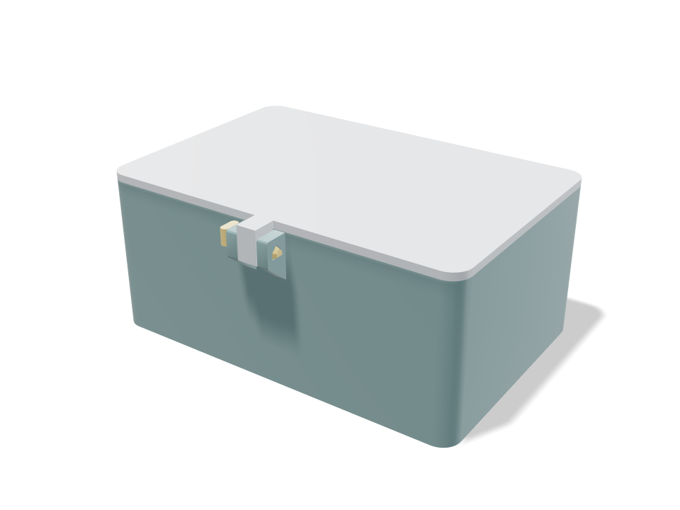
Parametric storage box with a compact locking pin
A locating lip seats the lid; a small removable pin holds it closed without a full-width latch housing. The assembly and use paths withdraw the pin before lifting the lid. Rounded corners, adjustable dividers and explicit fit controls keep the geometry useful. This is a digital prototype: print a local fit section and test retention before relying on it.
Ask for the sizes you want to tweak, e.g. “make the width adjustable”.

What Loftsmith can do
See what Loftsmith designs
Straight from the Loftsmith Workshop, every print check passed. Need a part this page can't make? Describe it and Loftsmith designs it for you.
Specs at the default size
Measured from the actual build on a Bambu Lab A1 in PLA. Every number updates live when you drag a slider above.
- Overall size
- 120 × 88 × 52 mm
- Parts
- 3
- Filament
- 91 g
- Print time
- 2 h 17 min
- Build plates
- 1
- Supports
- None needed
Engineering checks
- Lid clearance in the FDM sweet spot (0.15–0.35 mm/side)0.25 mm per side
- Seated lid clears the box and dividersLip engages 6 mm; divider tops have 0.4 mm vertical clearance.
- Localized pin housingOnly 14.1 mm of the front carries the lock; 7.7 mm projection.
- Separate locked solidsShared-axis pin gap 0.25 mm; calibrate it separately from the seating lip.
- Locked pin opposes lid liftA real 1 mm lifting attempt meets the pin.
- Pin fully withdrawsAllow 16.1 mm hand-access stroke to the left.
Adjustable sizes
| Setting | Default | Range |
|---|---|---|
| Length | 120 mm | 30–240 mm |
| Width | 80 mm | 30–240 mm |
| Height | 50 mm | 15–200 mm |
| Wall | 2 mm | 1.2–4 mm |
| Lid clearance (per side) | 0.25 mm | 0.1–0.6 mm |
| Dividers (lengthwise) | 1 | 0–6 |
| Corner radius | 6 mm | 1–20 mm |
| Locking pin width | 3.2 mm | 2.8–3.8 mm |
Parts list
| Part | Qty | Size (mm) | Filament | Time |
|---|---|---|---|---|
| box | 1 | 120 × 88 × 50 | 65 g | 1 h 33 min |
| lid | 1 | 120 × 88 × 11 | 26 g | 39 min |
| removable-pin | 1 | 18 × 6 × 5 | 0 g | 5 min |
How to make it
- Set the outer box dimensions and dividers; the local lock projects beyond the front.
- Start with 0.25 mm lid clearance and print an ear/lid/pin fit section.
- Withdraw the pin to the left before lifting the lid. Check hand access and the modeled path.
Print tips
- Print the box upright, the lid outer face down, and the pin flat underside down.
- Inspect the roofed bores and ear roots in the slicer. The removable pin has no back-out detent; transport needs qualified retention.
FAQ
Why does my lid not fit?
Adjust Lid clearance in 0.05 mm steps after a same-material fit test. The pin has its own running gap, at least 0.25 mm, and also needs testing.
Is the locking pin captive?
No. It removes completely and must be kept separately when the box is open. It has no detent or tested vibration resistance.
Need a shape that isn't in the catalog? Describe it in your own words with text to CAD
Design guides for this part: 3D printing tolerances: how much clearance each fit needs · Snap fit design for 3D printing: the one formula that stops them snapping off · STL vs 3MF: which file should you print from? · How to split a model that’s too big for your 3D printer · Wall thickness for 3D printing: the minimum and what to use · 3D printed threads: when they work and how to design them · Gridfinity dimensions: the 42 mm grid explained · 3D printer bed sizes (2026): what fits on every printer, and how many pieces a big part needs
Comments