3D printed threads: when they work and how to design them
A printed thread is either delightful, a jar lid that spins on to a satisfying stop, or maddening, a bolt that jams halfway. Size, pitch and clearance decide which, and the printer has strong opinions about all three.
Short answer
Print threads M6 and larger (M8 and up is easier) with the thread axis vertical. Give them clearance: model internal threads 0.2–0.4 mm larger in diameter and external threads 0.1–0.2 mm smaller, and chamfer the first turn. For lids and custom parts, a coarse thread with a 2–4 mm pitch prints far better than a fine metric one. Below M6, model a plain hole and use a heat-set insert, a nut or a tap.
Most CAD programs will draw a perfect M8 thread with two clicks, and most printers will turn it into something that jams after half a turn. The CAD thread isn’t wrong. It is drawn for a machine shop, where parts come out within a few hundredths of a millimetre. A printer works to a few tenths, and a thread has two surfaces that must miss each other all the way round.
Printed threads work well once you give them what they need: enough size, enough clearance, and a pitch the printer can draw.
What size prints
A thread’s teeth are small. An M4 thread has a pitch of 0.7 mm, so each tooth is about as tall as one or two extruded lines, and there is nothing for the printer to shape. The bigger the thread, the more lines each tooth gets.
| Size | Pitch | Tap drill (to cut the thread after printing) | Print the thread directly? |
|---|---|---|---|
| M4 | 0.7 mm | 3.3 mm | No: use an insert, nut or tap |
| M5 | 0.8 mm | 4.2 mm | No: use an insert, nut or tap |
| M6 | 1 mm | 5.0 mm | Possible, with care |
| M8 | 1.25 mm | 6.8 mm | Yes |
| M10 | 1.5 mm | 8.5 mm | Yes |
| M12 | 1.75 mm | 10.2 mm | Yes |
| M16 | 2 mm | 14.0 mm | Yes |
| M20 | 2.5 mm | 17.5 mm | Yes |
So the working rule for a 0.4 mm nozzle: below M6, don’t print the thread. At M6 it can work with careful clearances. From M8 up it works reliably.
Clearance for printed threads
Printed holes come out small and printed pegs come out large (the tolerance guide explains why), and a thread is a hole and a peg wound into a spiral. Model both at nominal size and the flanks collide.
- Internal threads (nuts, threaded holes): model 0.2–0.4 mm larger in diameter than nominal. An M10 internal thread becomes M10.2–M10.4.
- External threads (bolts, lids’ outer threads): model 0.1–0.2 mm smaller. An M10 bolt becomes 9.8–9.9 mm.
- Printing both parts? Put the clearance on both, so the total gap between flanks is 0.1–0.2 mm per side.
- Mating with a metal part? Put all the clearance on the printed side.
Most CAD thread tools have an offset or clearance setting for exactly this. Use it rather than scaling the part, which changes the pitch too.
Coarse beats fine
For your own parts, like a jar lid, a knob or a cap, you don’t need a metric thread at all. Design a coarse one. A pitch of 2–4 mm gives each tooth several millimetres of height, which prints cleanly, starts easily and tolerates dirt.
- Profile: a standard 60° thread has flanks only 30° from horizontal. That prints on small threads because each tooth is short, but a deep, coarse tooth droops. For big lid threads, use a 90° profile (flanks at 45°) or a buttress shape whose underside is at 45°. Avoid square threads, whose undersides are flat.
- Starts: a two-start thread closes in half as many turns for the same pitch, which is pleasant on a lid.
- Length: two to three full turns is plenty for a lid. More turns add friction, not strength.
- Lead-in: chamfer or taper the first half turn so the threads find each other instead of cross-threading.
Printing them well
- Axis vertical. Print threads with their axis pointing up, so every layer draws a complete cross-section of the thread. Lying down, the teeth become stacked overhangs and are much weaker.
- Fine layers. 0.2 mm or finer. Thinner layers resolve the flanks better, which matters most for small pitches.
- Solid walls. Use three to five perimeters so the teeth are made of solid plastic, not infill.
- Elephant foot. The first thread at the bed tends to be squashed. Chamfer the bottom or start the thread a millimetre above the bed.
When not to print the thread
For small sizes, and for joints that are assembled often or carry load, metal threads are better:
- Heat-set inserts give a metal thread in a clean hole. See the insert hole size chart.
- Captive nuts in a hex pocket are cheap and strong. See the screw hole guide.
- Tapping a printed hole works for M4 and up: model the hole at the tap drill size from the table above, print it with at least three or four perimeters, and cut the thread with a hand tap.
- Self-tapping screws into a slightly undersized hole are the quickest option for parts assembled once.
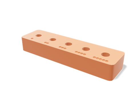 Heat-set insert testerFive hole sizes for M2–M5 heat-set inserts: the reliable alternative to small printed threads.60 × 16 × 9 mm · 5 g · 11 min
Questions people ask
Why don’t my 3D printed threads fit?
Usually because they were modelled at nominal size with no clearance. Printed internal threads come out small and external threads come out large, so the flanks collide. Model internal threads 0.2–0.4 mm oversize and external threads 0.1–0.2 mm undersize, and print with the axis vertical.
What is the smallest thread you can 3D print?
On a 0.4 mm nozzle, M6 is a sensible minimum and M8 or larger is reliable. M3 to M5 threads have flanks only a few extrusion widths tall and rarely print usefully; use heat-set inserts or nuts for those.
Can you tap a 3D printed hole?
Yes. Model the hole at the tap drill size (for example 5.0 mm for M6), print it with at least three or four perimeters, and cut the thread with a tap. It works well for M4 and larger in PETG and PLA.
What layer height is best for printed threads?
0.2 mm or finer. Thinner layers resolve the thread flanks more smoothly, which matters more for small pitches than for coarse lid threads.
Sources and method
The numbers come from Loftsmith’s CAD engine, which uses them to design and check every part it builds, and from the manufacturer and reference sources below. Every figure is checked against those sources and the engine’s own geometry. Found a mistake? Email [email protected] and we’ll fix it.