3D printed gears: module, teeth, backlash and material
Printed gears work far better than their reputation. What sinks most of them is not the plastic, but teeth that were never true involutes, two gears that don’t share a module, or no room left for the printer’s error.
Short answer
Pick one module (tooth size) for both gears; 1–1.5 mm suits small mechanisms and 2–3 mm carries more torque. Keep at least 17 teeth on a 20° gear to avoid undercut, set the centre distance to module × (teeth of gear 1 + teeth of gear 2) ÷ 2, and add about 0.1–0.2 mm of backlash for FDM. Print gears flat so each tooth is formed within a layer, use PETG or nylon for anything that runs for hours, and use true involute teeth, not a drawn approximation.
Search for a gear, download two that look about right, and there is a good chance they will grind, jump teeth or lock solid. Gears are unforgiving that way: two gears only mesh if they were designed for each other, down to the shape of the tooth.
The good news is that a whole gear is defined by a handful of numbers, and once you know them, designing a printable pair takes minutes. Printed gears run happily in clocks, robots, winches and extruders when those numbers are right.
The numbers that define a gear
- Module (m): the size of the teeth, in millimetres. Two gears must share the same module to mesh. It is the single most important number.
- Tooth count (z): sets the gear’s size and the ratio of a pair.
- Pressure angle: the slope of the tooth’s working face. 20° is the standard; use it for both gears.
- Face width: how wide the teeth are along the axle. Wider spreads the load.
Everything else follows from module and tooth count:
pitch diameter = m × z · outside diameter = m × (z + 2) · tooth depth = 2.25 × m
Loftsmith’s default spur gear has m = 1.5 mm and z = 24: a pitch diameter of 36 mm and an outside diameter of 39 mm, which is exactly the 39 mm the model measures.
| Module | Tooth depth | Good for |
|---|---|---|
| 1 mm | 2.25 mm | Small mechanisms, toys, light-duty drives |
| 1.5 mm | 3.4 mm | General mechanisms; a good first choice |
| 2 mm | 4.5 mm | Motors under load, winches |
| 3 mm | 6.75 mm | High torque, large slow gears |
Designing a pair
Say we want to slow a motor down by 1.5 : 1 with the default gear. Pair the 24-tooth gear with a 36-tooth gear of the same module. The ratio is 36 ÷ 24 = 1.5, and the axles must sit exactly this far apart:
centre distance = m × (z₁ + z₂) ÷ 2 = 1.5 × (24 + 36) ÷ 2 = 45 mm
Get the centre distance right and the teeth mesh at their pitch circles, where they are designed to roll. Too close and they bind; too far and they chatter and skip.
Use real involute teeth, generated from the base circle, not an approximation drawn with arcs. Involute teeth keep rolling smoothly even when the centre distance is slightly off, which is exactly the forgiveness a printed gear needs.
Backlash for FDM
Backlash is the small gap between meshing teeth. Metal gears need very little. Printed gears need more, because every tooth is a little off and the errors add up around the gear.
Start with about 0.1–0.2 mm; Loftsmith’s gear generator defaults to 0.15 mm, built into the tooth thickness. If a pair binds at one spot as it turns, add backlash. If it feels loose and clacks when it reverses, remove some. Check the axle holes too: a sloppy axle adds far more play than the teeth do.
Printing gears
- Print flat. Lay the gear on its face so every layer contains a complete outline of the teeth. Printed standing up, the teeth would be stacks of layers that snap off along their lines.
- Solid teeth. Use enough perimeters that the teeth print solid, typically four or more.
- Watch the first layer. Elephant foot swells the bottom of every tooth. Use elephant foot compensation or a small chamfer on the bottom edge.
- Consider herringbone. A herringbone gear has V-shaped teeth. It runs smoother, pushes no load along the axle, and stays aligned on its own. It prints without support when printed flat.
The default gear (8 mm face width) uses about 6 g of PLA and prints in about 13 minutes on an A1, so a test pair is cheap.
Material
| Material | Wear | Notes |
|---|---|---|
| PLA | Fair | Crisp teeth; fine for prototypes and light loads. Wears and softens with friction heat. |
| PETG | Good | Tougher and less brittle; a sensible default for working mechanisms. |
| Nylon | Best | Tough and slippery; the choice for gears that run for hours. Must be printed dry. |
A dab of grease or dry PTFE lubricant helps any printed gear pair run quieter and last longer. Mixing materials also works: a nylon pinion running against a PLA gear wears better than two PLA gears. The filament guide compares the common materials in more detail.
Fixing the gear to its shaft
A round bore on a round shaft slips. Choose one of these instead:
- D-shaft bore, matching a motor shaft’s flat, with about 0.1–0.2 mm clearance.
- Set screw in a hub. The generator’s hub has a 2.6 mm hole that an M3 screw taps into; for gears you take on and off, swap it for a trapped nut or a heat-set insert.
- Press fit on a knurled shaft, for small, light gears.
For the hub’s screw and nut sizes, see the screw hole guide, and for bore clearances, the tolerance guide.
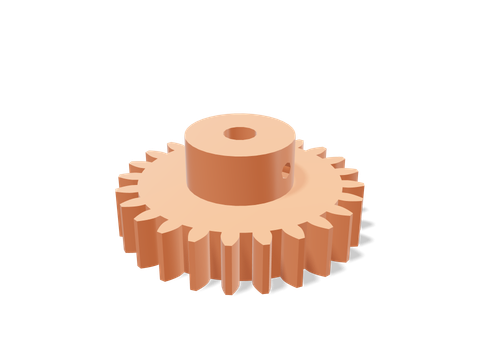 Spur gearTrue involute spur gears with module, teeth, face width, bore, backlash and a set-screw hub.39 × 39 × 16 mm · 6 g · 13 min
Questions people ask
What module should I use for 3D printed gears?
1–1.5 mm for small mechanisms and toys, 2–3 mm for gears that carry real torque. Bigger teeth are stronger and more tolerant of printing errors, at the cost of a larger gear for the same tooth count.
How much backlash do 3D printed gears need?
About 0.1–0.2 mm on an FDM printer. Less and the gears bind as tooth errors add up; more and the mechanism feels sloppy. Loftsmith’s gear generator defaults to 0.15 mm.
What is the best filament for 3D printed gears?
Nylon is the most wear-resistant and slippery. PETG is a good, easy all-rounder. PLA works for light loads and prototypes but wears and can creep under constant load or heat.
Why does a gear need at least 17 teeth?
With the standard 20° pressure angle, a gear with fewer than 17 teeth has its tooth roots cut away (undercut) when it is generated, which weakens the teeth and shortens their contact. Profile shift can fix it, but 17 or more is the simple rule.
Sources and method
The numbers come from Loftsmith’s CAD engine, which uses them to design and check every part it builds, and from the manufacturer and reference sources below. Every figure is checked against those sources and the engine’s own geometry. Found a mistake? Email [email protected] and we’ll fix it.