Un ala volante RC que Loftsmith diseñó con un solo prompt
Nadie la dibujó. Le dimos a Loftsmith una sola frase, "A 3D printable RC flying wing" (un ala volante RC imprimible en 3D), sin medidas, piezas ni hardware, y planificó el avión en siete etapas y lo construyó por su cuenta: un ala propulsora de 1 m con 37° de flecha, impresa entera en PLA en una Bambu Lab A1 y dimensionada para el kit de iniciación de siempre (motor 2212, ESC de 30 A, LiPo 3S 2200 y dos servos MG90S). La góndola central aloja la batería bajo una tapa magnética enrasada; cada lado tiene dos paneles de ala impresos de pie sobre su cara de raíz, con pieles de 0,8 mm sobre almas internas, montados en un larguero de carbono de 8 mm y conectores de 6 mm con 2° de torsión. Los elevones se mueven ±15° sobre bisagras CA, accionados por servos tumbados en los paneles interiores, y el motor va en una góndola detrás del borde de salida. Lo que ves aquí es exactamente lo que hizo, sin editar, incluidas sus propias notas honestas: pesa mucho para su tamaño y necesita lastre en el morro para centrarla. Para nuestra ala refinada a mano, mira el generador de ala volante RC.
Hecho por Loftsmith con un solo prompt
“A 3D printable RC flying wing”
Esto es exactamente lo que Loftsmith diseñó a partir del prompt de abajo, sin editar: planificó el proyecto, escribió y reconstruyó el modelo según llegaban las revisiones y lo terminó por su cuenta.
- Turnos de diseño
- 22
- Construcciones (14 correctas)
- 19
- Tokens (entrada / salida)
- 3.23M / 0.52M
- Créditos de Loftsmith
- 271
- Revisiones de ingeniería superadas
- 68
Diseñado el 2026-09-28. A precios del plan Pro, 271 créditos salen por unos 54 $.
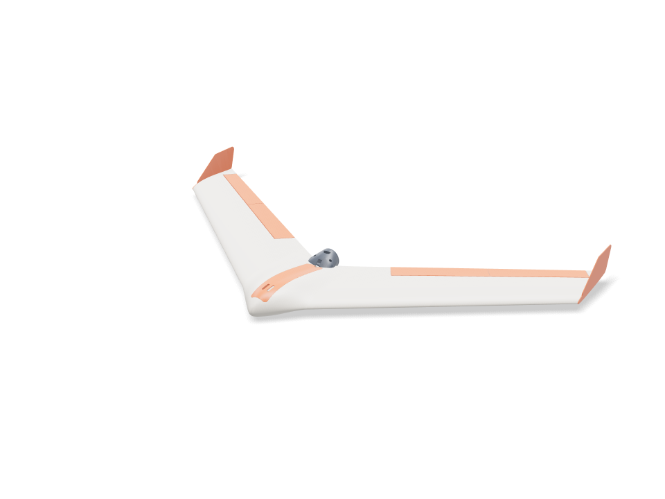
Ask for the sizes you want to tweak, e.g. “make the width adjustable”.
Especificaciones con el tamaño por defecto
Medido en la construcción real en una Bambu Lab A1 con PLA. Cada número se actualiza al momento cuando mueves un deslizador de arriba.
- Tamaño total
- 1003 × 553 × 85 mm
- Piezas
- 18
- Filamento
- 677 g
- Tiempo de impresión
- 19 h 19 min
- Placas
- 6
- Soportes
- No hacen falta
Revisiones de ingeniería
Los nombres de las revisiones y de los parámetros vienen del motor de CAD y se muestran en inglés.
- Battery reaches the balance pointbalance at 20.0 % MAC = 212 mm behind the root LE needs the battery centre at y 68; the bay slides it 65 to 96 mm
- Nose weight fits the nose tip40 g of lead (26 x 7 x 20 mm) ahead of the battery, overlap 0.0 mm³; room for 57 g
- Nose weight stays modest40 g of lead = 3.7 % of all-up weight (limit 5 %); LW-PLA wing panels are the next way to cut it
- Battery fits the bay, front and backoverlap 0.0 / 0.0 mm³; 31 mm of slide, loads straight down through a 40 mm wide opening
- ESC and receiver fit their side baysoverlap 0.0 / 0.0 mm³; they slide in sideways under the skin, before the battery
- Spar tunnel stays inside the joint face1.6 mm of PLA above and below the 8 mm tube at the panel joint (75 % chord)
- Wing loading1083 g all-up on 18.6 dm² = 58 g/dm²; stall about 11.5 m/s (CL 0.7). Limit 60 g/dm² and a stall under 12 m/s for a firm hand launch; the plan's 35 g/dm² is not reachable with 0.8 mm PLA skins
- Enough thrust to hand launchabout 800 g static thrust (estimate) for 1083 g all-up = 0.74 : 1 (want 0.6+)
- Carbon spar at the panel root (4 g pull-up)80 MPa in an 8x6 mm carbon tube (allow ~250 MPa)
- Joiner at the panel joint (4 g pull-up)57 MPa in a 6x4 mm carbon tube (allow ~250 MPa); the glued PLA joint face shares the load
- Spar and joiner buried in the wing1.2 mm of PLA round the 8 mm spar out to 230 mm (100.0 % inside) and round the 6 mm joiner, 60 mm into each panel (100.0 %)
- Spar and joiner don't clashthe 8 mm spar stops 40 mm short of the panel joint on its own shear web; the joiner rides the 40 % chord web behind it
- Anti-twist pins buried at both joints3 mm carbon pins, 11 mm into each face, bosses 100.0 % inside the skin
- Internal webs print without supportdiagonal webs lean at most 27° from vertical with the panel standing on its root
- Wing inner panel fits the A1 bed190 mm tall standing on its root; 274 x 21 mm footprint needs 209 mm turned 45°
- Wing inner panel stands steady while printingits centre of mass (y 210) sits 59 mm inside the root face (y 60 to 269); print with a 5 mm brim
- Wing outer panel fits the A1 bed230 mm tall standing on its root; 323 x 19 mm footprint needs 242 mm turned 45°
- Wing outer panel stands steady while printingits centre of mass (y 358) sits 28 mm inside the root face (y 203 to 386); print with a 5 mm brim
- Fits the A1 bed standing on its side160 mm tall; 282 x 51 mm footprint needs 236 mm turned 45°
- Centre filament target153 g of PLA (target 170 g)
- Wing panel filament target361 g of PLA for all four panels (target 400 g)
- Elevon sizeabout 3.30 dm² = 18 % of the wing (aim 12-25 %), 28 % of the local chord
- Elevons swing ±15° clear of the wingtightest gap at the hinge face 0.9 mm (V below and Λ above the hinge line at 22°); ends cut square to the hinge with 0.8 mm gaps
- Hinge pockets stay under the skin1.0 mm of top skin over the thinnest end of the strip pockets
- Hinge strip flex0.8 mm bought CA hinge bends over 3.6 mm of free length: 2.9 % surface strain at 15° (keep under ~10 % for long life)
- Elevon halves fit the A1 bed on end201 / 201 mm tall standing on their square ends
- Elevon joint pin buried3 mm carbon pin, 11 mm into each half; boss 100.0 % inside the skin
- Servo fits the wing depthMG90S lying flat: 1.4 mm of top skin over the pocket, 1.1 mm above the cover plate
- Servo pocket clear of spar and joinerpocket walls vs spar / joiner sleeves: 0.00 / 0.00 mm³
- Servo travel for ±15° elevonservo horn hole 12.3 mm from the shaft, control horn hole 15.1 mm below the hinge: ±15° needs ±19° of servo
- Servo torque (estimate)about 4.9 N·cm at 22 m/s full throw (hinge-moment coefficient 0.25 assumed) vs ~18 N·cm MG90S stall; keep under half
- Control horn at servo stall2.3 MPa at the horn root with 15 N on the pushrod (servo stalled), along the layers; allow 16.7
- Control horn swings clear of the wingoverlap at +15 / 0 / -15°: 0.0 / 0.0 / 0.2 mm³
- Pushrod runs clear74 mm pushrod under the skin; 0.00 mm³ overlap with the wing, cover, elevon and horn
- Servo lead channel stays inside the skin11 x 6 mm channel for the 15 x 8 x 4.2 mm plug, 135 mm long: 100.0 % inside with its 0.8 mm walls
- Servo cover sits flushthe flat plate stands up to 0.7 mm proud of the curved skin at its edges
- Servo and cover are fastenedservo: 2 tab screws 6 mm into the cover lugs; cover: 2x M2 into heat-set inserts with 1.6 mm boss wall
- Prop clears the trailing edgeblade tips run 5.0 mm behind the swept trailing edge at 102 mm radius; swept disc overlaps the airframe by 0.0 mm³
- Spar covered where the tail thins100.0 % of a 1.2 mm skin round the 8 mm spar is enclosed across the middle 64 mm, with the pod fitted
- Pod bolts clamp solid PLAthe centre tail is 100 % solid round each M3 bolt, so clamping cannot crush a hollow skin
- Pod carries the motor on a hard landing0.14 MPa across the layers of the 1.2 mm PLA shell at a 10 g landing (motor + prop on a 43 mm arm); allow 5.0
- Prop parked clear on landingwith the ESC brake set the prop stops level; its hub bottom sits 15 mm above the pod belly, which touches down first
- Motor and plate are fastenedmotor: 4x M3x6 through the plate into its 16x19 holes; plate: 3x M3x8 into heat-set inserts, 5.3 mm from the plate edge (need 5.1), heads 0.3 mm clear of the motor can
- Pod filament target26 g of PLA for the pod and plate (target 40 g)
- Winglet size (yaw stability)two winglets add 1.14 dm² = 6.1 % of the wing area (aim 6-9 %)
- Winglet pegs keyed into a solid tip2x 4 mm square pegs, 7 mm deep, 0.15 mm glue gap; 4.3 mm of tip above and below each pocket; bosses 99.9 % inside the skin
- Winglet root in a side gust1.4 MPa where the plate leaves the tip (1.7 N side load at 22 m/s, CL 1, taken on half the tip chord), along the layers; allow 16.7
- Winglet filament target14.7 g of PLA each (target 16 g)
- Winglet fits the A1 bed163 x 68 mm lying on its outer face
- Hatch sits flush without clashinghatch vs centre overlap 0.05 mm³; top cut from the pod surface, 0.2 mm gap all round, resting on 2.5 mm side ledges and the rear bulkhead; 17 g
- Hatch stays on in flightsuction about 2.3 N at 22 m/s (pressure coefficient -1 assumed); the 6 mm front tongue takes half, two 6x3 mm magnet pairs hold ~10 N at the back
- Battery held downvelcro on the cradle ribs sets its slide position; the hatch skin or its keeper rails sit 1.2-1.5 mm above the battery along its whole length (a 2 mm foam strip on the rails takes up the play)
- Motor wires pass to the pod5.7 mm tall x 8 mm wide gap between the magnet pads, over the bulkhead and out the 7 mm rear notch into the pod slot: room for three 16 AWG leads
- Magnet pockets stay inside the bulkhead3.8 mm of PLA under each 6x3 mm magnet pocket
- battery 3S 2200 goes in25 poses along its path clear of every part.
- ESC 30 A goes in42 poses along its path clear of every part.
- receiver goes in41 poses along its path clear of every part.
- nose weight (lead) goes in36 poses along its path clear of every part.
- servo MG90S R goes in23 poses along its path clear of every part.
- servo MG90S L goes in23 poses along its path clear of every part.
- servo plug R goes in60 poses along its path clear of every part.
- servo plug L goes in60 poses along its path clear of every part.
- driver: servo tab screw (bench) goes in15 poses along its path clear of every part.
- driver: cover screw goes in15 poses along its path clear of every part.
- motor 2212 goes in20 poses along its path clear of every part.
- motor lead (3.5 mm bullet) goes in18 poses along its path clear of every part.
- driver: motor plate screw goes in15 poses along its path clear of every part.
- driver: pod bolt goes in15 poses along its path clear of every part.
Medidas ajustables
| Parámetro | Por defecto | Rango |
|---|---|---|
| Wingspan | 1000 mm | 800–1020 mm |
| Leading-edge sweep | 37 ° | 32–38 ° |
| Wing root chord | 220 mm | 190–225 mm |
| Tip chord | 150 mm | 110–170 mm |
| Centre half-width | 80 mm | 65–85 mm |
| Pod thickness | 22 % | 18–24 % |
| Balance point | 20 % MAC | 15–22 % MAC |
| Wing panel skin | 0.8 mm | 0.8–1.2 mm |
| Tip washout | 2 ° | 0–4 ° |
| Elevon chord | 28 % chord | 22–32 % chord |
| Elevon inboard end | 150 mm | 130–190 mm |
| Winglet height | 52 mm | 40–70 mm |
Lista de piezas
| Pieza | Cant. | Tamaño (mm) | Filamento | Tiempo |
|---|---|---|---|---|
| center-section | 1 | 204 × 203 × 160 | 152 g | 3 h 37 min |
| wing-inner-R | 1 | 200 × 197 × 190 | 95 g | 2 h 25 min |
| wing-outer-R | 1 | 233 × 227 × 230 | 86 g | 2 h 19 min |
| wing-inner-L | 1 | 197 × 200 × 190 | 95 g | 2 h 25 min |
| wing-outer-L | 1 | 227 × 233 × 230 | 86 g | 2 h 19 min |
| elevon-inner-R | 1 | 47 × 12 × 200 | 24 g | 54 min |
| elevon-outer-R | 1 | 42 × 10 × 200 | 20 g | 50 min |
| elevon-inner-L | 1 | 47 × 12 × 200 | 24 g | 54 min |
| elevon-outer-L | 1 | 42 × 10 × 200 | 20 g | 50 min |
| servo-cover-R | 1 | 63 × 51 × 15 | 3 g | 10 min |
| servo-cover-L | 1 | 63 × 51 × 15 | 3 g | 10 min |
| control-horn-R | 1 | 20 × 13 × 2 | 0 g | 5 min |
| control-horn-L | 1 | 20 × 13 × 2 | 0 g | 5 min |
| motor-mount | 1 | 62 × 45 × 45 | 19 g | 33 min |
| motor-plate | 1 | 45 × 45 × 3 | 4 g | 9 min |
| winglet-R | 1 | 68 × 163 × 9 | 15 g | 24 min |
| winglet-L | 1 | 68 × 163 × 9 | 15 g | 24 min |
| hatch | 1 | 40 × 27 × 203 | 17 g | 46 min |
Cómo hacerlo
- Imprime primero la sección central y prueba el ajuste del larguero, la batería y la tapa.
- Pega con epoxi los pasadores de raíz, desliza la góndola del motor sobre la cola, luego pasa el larguero de 8 mm por el centro y los dos paneles interiores y pega las caras de raíz.
- Pega los conectores de 6 mm y los pasadores exteriores en los paneles interiores, luego desliza los paneles exteriores por los conectores y pégalos.
- Pega las dos mitades de cada elevón sobre un pasador de 3 mm. Mete las bisagras CA en los alojamientos del ala y del elevón, comprueba el recorrido de ±15° y luego deja que penetre cianoacrilato fino.
- Atornilla cada servo a su tapa en la mesa, pasa el cable por el canal hasta el hueco y fija la tapa con 2x M2x6. Pega los horns de mando en las ranuras de los elevones y monta las varillas con doblez en Z.
- Atornilla el motor a su placa, fija la góndola con 2x M3x12, monta la placa con 3x M3x8, pega los winglets con sus espigas y ajusta el centro de gravedad con la batería y lastre en el morro antes del primer vuelo.
Consejos de impresión
- Todas las piezas en PLA a 0,2 mm, 2 perímetros y 15 % de relleno, sin soportes.
- Añade un brim de 5 mm en las piezas altas y baja la velocidad de los perímetros exteriores en los paneles del ala; los bordes de salida finos son normales.
- La góndola del motor en PLA se ablanda hacia los 55 °C: si tras un vuelo el motor quema demasiado para sujetarlo, reimprime la góndola y la placa en PETG.
Preguntas frecuentes
¿De verdad salió de un solo prompt?
Sí. La única entrada fue "A 3D printable RC flying wing" (un ala volante RC imprimible en 3D), con una Bambu Lab A1 y PLA seleccionados. Loftsmith planificó siete etapas, escribió y reconstruyó el modelo 19 veces a medida que llegaban las revisiones de ingeniería y lo dio por terminado. El modelo y las notas de esta página son su resultado sin editar.
¿Cuánto costó diseñarla?
22 turnos de diseño, 3,2 millones de tokens de entrada y 0,52 millones de salida: 271 créditos de Loftsmith, unos 54 $ a precios del plan Pro. Para un proyecto grande como este existe el paquete de créditos Gran proyecto.
¿Volará?
Está diseñada para ello y pasa todas las revisiones de ingeniería, pero no se ha probado en vuelo y pesa mucho para su tamaño (unos 58 g/dm²), así que necesita unos 40 g de lastre en el morro y un lanzamiento a mano firme. Comprueba primero a mano el centro de gravedad y el recorrido de los elevones.
Comments