Ein RC-Nurflügler, den Loftsmith aus einem einzigen Prompt konstruiert hat
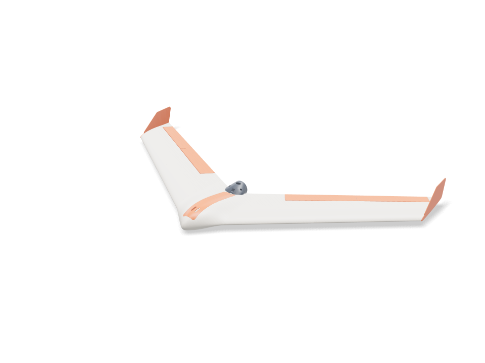
Das hat niemand gezeichnet. Wir haben Loftsmith einen einzigen Satz gegeben, "A 3D printable RC flying wing" (ein 3D-druckbarer RC-Nurflügler), ohne Maße, Teile oder Hardware, und es hat das Flugzeug in sieben Phasen geplant und selbstständig gebaut: einen Nurflügler mit Druckantrieb, 1 m Spannweite und 37° Pfeilung, komplett in PLA auf einem Bambu Lab A1 gedruckt und ausgelegt für das übliche Einsteiger-Set (2212-Motor, 30-A-Regler, 3S-2200-LiPo und zwei MG90S-Servos). Die Mittelgondel nimmt den Akku unter einer bündigen Magnetklappe auf; jede Seite hat zwei Flügelsegmente, stehend auf der Wurzelfläche gedruckt, mit 0,8 mm Haut über inneren Stegen, auf einem 8-mm-Carbonholm und 6-mm-Verbindern mit 2° Schränkung. Die Elevons schlagen an CA-Scharnieren ±15° aus, angesteuert von Servos, die flach in den inneren Segmenten liegen, und der Motor sitzt in einer Gondel hinter der Endleiste. Was du hier siehst, ist genau das, was es gebaut hat, unbearbeitet, samt seinen eigenen ehrlichen Anmerkungen: Für seine Größe ist er schwer und braucht Blei in der Nase, um den Schwerpunkt zu treffen. Unseren von Hand verfeinerten Flügel findest du beim RC-Nurflügler-Generator.
Von Loftsmith aus einem einzigen Prompt gebaut
“A 3D printable RC flying wing”
Genau das hat Loftsmith aus dem Prompt unten konstruiert, unbearbeitet: Es hat den Bau geplant, das Modell geschrieben und neu gebaut, sobald die Prüfungen zurückkamen, und es selbstständig fertiggestellt.
- Konstruktions-Turns
- 22
- Builds (14 bestanden)
- 19
- Tokens (Input / Output)
- 3.23M / 0.52M
- Loftsmith-Credits
- 271
- Bestandene Konstruktionsprüfungen
- 68
Konstruiert am 2026-09-28. Zu Preisen des Pro-Plans entsprechen 271 Credits rund 54 $.
Ask for the sizes you want to tweak, e.g. “make the width adjustable”.
Daten bei Standardgröße
Gemessen am echten Build auf einem Bambu Lab A1 in PLA. Jede Zahl aktualisiert sich live, wenn du oben an einem Regler ziehst.
- Gesamtgröße
- 1003 × 553 × 85 mm
- Teile
- 18
- Filament
- 677 g
- Druckzeit
- 19 h 19 min
- Druckplatten
- 6
- Stützstrukturen
- Nicht nötig
Technische Prüfungen
Namen von Prüfungen und Parametern kommen direkt aus der CAD-Engine und sind auf Englisch.
- Battery reaches the balance pointbalance at 20.0 % MAC = 212 mm behind the root LE needs the battery centre at y 68; the bay slides it 65 to 96 mm
- Nose weight fits the nose tip40 g of lead (26 x 7 x 20 mm) ahead of the battery, overlap 0.0 mm³; room for 57 g
- Nose weight stays modest40 g of lead = 3.7 % of all-up weight (limit 5 %); LW-PLA wing panels are the next way to cut it
- Battery fits the bay, front and backoverlap 0.0 / 0.0 mm³; 31 mm of slide, loads straight down through a 40 mm wide opening
- ESC and receiver fit their side baysoverlap 0.0 / 0.0 mm³; they slide in sideways under the skin, before the battery
- Spar tunnel stays inside the joint face1.6 mm of PLA above and below the 8 mm tube at the panel joint (75 % chord)
- Wing loading1083 g all-up on 18.6 dm² = 58 g/dm²; stall about 11.5 m/s (CL 0.7). Limit 60 g/dm² and a stall under 12 m/s for a firm hand launch; the plan's 35 g/dm² is not reachable with 0.8 mm PLA skins
- Enough thrust to hand launchabout 800 g static thrust (estimate) for 1083 g all-up = 0.74 : 1 (want 0.6+)
- Carbon spar at the panel root (4 g pull-up)80 MPa in an 8x6 mm carbon tube (allow ~250 MPa)
- Joiner at the panel joint (4 g pull-up)57 MPa in a 6x4 mm carbon tube (allow ~250 MPa); the glued PLA joint face shares the load
- Spar and joiner buried in the wing1.2 mm of PLA round the 8 mm spar out to 230 mm (100.0 % inside) and round the 6 mm joiner, 60 mm into each panel (100.0 %)
- Spar and joiner don't clashthe 8 mm spar stops 40 mm short of the panel joint on its own shear web; the joiner rides the 40 % chord web behind it
- Anti-twist pins buried at both joints3 mm carbon pins, 11 mm into each face, bosses 100.0 % inside the skin
- Internal webs print without supportdiagonal webs lean at most 27° from vertical with the panel standing on its root
- Wing inner panel fits the A1 bed190 mm tall standing on its root; 274 x 21 mm footprint needs 209 mm turned 45°
- Wing inner panel stands steady while printingits centre of mass (y 210) sits 59 mm inside the root face (y 60 to 269); print with a 5 mm brim
- Wing outer panel fits the A1 bed230 mm tall standing on its root; 323 x 19 mm footprint needs 242 mm turned 45°
- Wing outer panel stands steady while printingits centre of mass (y 358) sits 28 mm inside the root face (y 203 to 386); print with a 5 mm brim
- Fits the A1 bed standing on its side160 mm tall; 282 x 51 mm footprint needs 236 mm turned 45°
- Centre filament target153 g of PLA (target 170 g)
- Wing panel filament target361 g of PLA for all four panels (target 400 g)
- Elevon sizeabout 3.30 dm² = 18 % of the wing (aim 12-25 %), 28 % of the local chord
- Elevons swing ±15° clear of the wingtightest gap at the hinge face 0.9 mm (V below and Λ above the hinge line at 22°); ends cut square to the hinge with 0.8 mm gaps
- Hinge pockets stay under the skin1.0 mm of top skin over the thinnest end of the strip pockets
- Hinge strip flex0.8 mm bought CA hinge bends over 3.6 mm of free length: 2.9 % surface strain at 15° (keep under ~10 % for long life)
- Elevon halves fit the A1 bed on end201 / 201 mm tall standing on their square ends
- Elevon joint pin buried3 mm carbon pin, 11 mm into each half; boss 100.0 % inside the skin
- Servo fits the wing depthMG90S lying flat: 1.4 mm of top skin over the pocket, 1.1 mm above the cover plate
- Servo pocket clear of spar and joinerpocket walls vs spar / joiner sleeves: 0.00 / 0.00 mm³
- Servo travel for ±15° elevonservo horn hole 12.3 mm from the shaft, control horn hole 15.1 mm below the hinge: ±15° needs ±19° of servo
- Servo torque (estimate)about 4.9 N·cm at 22 m/s full throw (hinge-moment coefficient 0.25 assumed) vs ~18 N·cm MG90S stall; keep under half
- Control horn at servo stall2.3 MPa at the horn root with 15 N on the pushrod (servo stalled), along the layers; allow 16.7
- Control horn swings clear of the wingoverlap at +15 / 0 / -15°: 0.0 / 0.0 / 0.2 mm³
- Pushrod runs clear74 mm pushrod under the skin; 0.00 mm³ overlap with the wing, cover, elevon and horn
- Servo lead channel stays inside the skin11 x 6 mm channel for the 15 x 8 x 4.2 mm plug, 135 mm long: 100.0 % inside with its 0.8 mm walls
- Servo cover sits flushthe flat plate stands up to 0.7 mm proud of the curved skin at its edges
- Servo and cover are fastenedservo: 2 tab screws 6 mm into the cover lugs; cover: 2x M2 into heat-set inserts with 1.6 mm boss wall
- Prop clears the trailing edgeblade tips run 5.0 mm behind the swept trailing edge at 102 mm radius; swept disc overlaps the airframe by 0.0 mm³
- Spar covered where the tail thins100.0 % of a 1.2 mm skin round the 8 mm spar is enclosed across the middle 64 mm, with the pod fitted
- Pod bolts clamp solid PLAthe centre tail is 100 % solid round each M3 bolt, so clamping cannot crush a hollow skin
- Pod carries the motor on a hard landing0.14 MPa across the layers of the 1.2 mm PLA shell at a 10 g landing (motor + prop on a 43 mm arm); allow 5.0
- Prop parked clear on landingwith the ESC brake set the prop stops level; its hub bottom sits 15 mm above the pod belly, which touches down first
- Motor and plate are fastenedmotor: 4x M3x6 through the plate into its 16x19 holes; plate: 3x M3x8 into heat-set inserts, 5.3 mm from the plate edge (need 5.1), heads 0.3 mm clear of the motor can
- Pod filament target26 g of PLA for the pod and plate (target 40 g)
- Winglet size (yaw stability)two winglets add 1.14 dm² = 6.1 % of the wing area (aim 6-9 %)
- Winglet pegs keyed into a solid tip2x 4 mm square pegs, 7 mm deep, 0.15 mm glue gap; 4.3 mm of tip above and below each pocket; bosses 99.9 % inside the skin
- Winglet root in a side gust1.4 MPa where the plate leaves the tip (1.7 N side load at 22 m/s, CL 1, taken on half the tip chord), along the layers; allow 16.7
- Winglet filament target14.7 g of PLA each (target 16 g)
- Winglet fits the A1 bed163 x 68 mm lying on its outer face
- Hatch sits flush without clashinghatch vs centre overlap 0.05 mm³; top cut from the pod surface, 0.2 mm gap all round, resting on 2.5 mm side ledges and the rear bulkhead; 17 g
- Hatch stays on in flightsuction about 2.3 N at 22 m/s (pressure coefficient -1 assumed); the 6 mm front tongue takes half, two 6x3 mm magnet pairs hold ~10 N at the back
- Battery held downvelcro on the cradle ribs sets its slide position; the hatch skin or its keeper rails sit 1.2-1.5 mm above the battery along its whole length (a 2 mm foam strip on the rails takes up the play)
- Motor wires pass to the pod5.7 mm tall x 8 mm wide gap between the magnet pads, over the bulkhead and out the 7 mm rear notch into the pod slot: room for three 16 AWG leads
- Magnet pockets stay inside the bulkhead3.8 mm of PLA under each 6x3 mm magnet pocket
- battery 3S 2200 goes in25 poses along its path clear of every part.
- ESC 30 A goes in42 poses along its path clear of every part.
- receiver goes in41 poses along its path clear of every part.
- nose weight (lead) goes in36 poses along its path clear of every part.
- servo MG90S R goes in23 poses along its path clear of every part.
- servo MG90S L goes in23 poses along its path clear of every part.
- servo plug R goes in60 poses along its path clear of every part.
- servo plug L goes in60 poses along its path clear of every part.
- driver: servo tab screw (bench) goes in15 poses along its path clear of every part.
- driver: cover screw goes in15 poses along its path clear of every part.
- motor 2212 goes in20 poses along its path clear of every part.
- motor lead (3.5 mm bullet) goes in18 poses along its path clear of every part.
- driver: motor plate screw goes in15 poses along its path clear of every part.
- driver: pod bolt goes in15 poses along its path clear of every part.
Anpassbare Maße
| Einstellung | Standard | Bereich |
|---|---|---|
| Wingspan | 1000 mm | 800–1020 mm |
| Leading-edge sweep | 37 ° | 32–38 ° |
| Wing root chord | 220 mm | 190–225 mm |
| Tip chord | 150 mm | 110–170 mm |
| Centre half-width | 80 mm | 65–85 mm |
| Pod thickness | 22 % | 18–24 % |
| Balance point | 20 % MAC | 15–22 % MAC |
| Wing panel skin | 0.8 mm | 0.8–1.2 mm |
| Tip washout | 2 ° | 0–4 ° |
| Elevon chord | 28 % chord | 22–32 % chord |
| Elevon inboard end | 150 mm | 130–190 mm |
| Winglet height | 52 mm | 40–70 mm |
Teileliste
| Teil | Anz. | Größe (mm) | Filament | Zeit |
|---|---|---|---|---|
| center-section | 1 | 204 × 203 × 160 | 152 g | 3 h 37 min |
| wing-inner-R | 1 | 200 × 197 × 190 | 95 g | 2 h 25 min |
| wing-outer-R | 1 | 233 × 227 × 230 | 86 g | 2 h 19 min |
| wing-inner-L | 1 | 197 × 200 × 190 | 95 g | 2 h 25 min |
| wing-outer-L | 1 | 227 × 233 × 230 | 86 g | 2 h 19 min |
| elevon-inner-R | 1 | 47 × 12 × 200 | 24 g | 54 min |
| elevon-outer-R | 1 | 42 × 10 × 200 | 20 g | 50 min |
| elevon-inner-L | 1 | 47 × 12 × 200 | 24 g | 54 min |
| elevon-outer-L | 1 | 42 × 10 × 200 | 20 g | 50 min |
| servo-cover-R | 1 | 63 × 51 × 15 | 3 g | 10 min |
| servo-cover-L | 1 | 63 × 51 × 15 | 3 g | 10 min |
| control-horn-R | 1 | 20 × 13 × 2 | 0 g | 5 min |
| control-horn-L | 1 | 20 × 13 × 2 | 0 g | 5 min |
| motor-mount | 1 | 62 × 45 × 45 | 19 g | 33 min |
| motor-plate | 1 | 45 × 45 × 3 | 4 g | 9 min |
| winglet-R | 1 | 68 × 163 × 9 | 15 g | 24 min |
| winglet-L | 1 | 68 × 163 × 9 | 15 g | 24 min |
| hatch | 1 | 40 × 27 × 203 | 17 g | 46 min |
So wird’s gemacht
- Zuerst das Mittelteil drucken und Holm, Akku und Klappe probeweise einpassen.
- Die Wurzelstifte mit Epoxid einkleben, die Motorgondel über das Heck schieben, dann den 8-mm-Holm durch Mittelteil und beide inneren Segmente schieben und die Wurzelflächen verkleben.
- Die 6-mm-Verbinder und die äußeren Stifte in die inneren Segmente kleben, dann die äußeren Segmente auf die Verbinder schieben und verkleben.
- Die beiden Hälften jedes Elevons auf einem 3-mm-Stift zusammenkleben. Die CA-Scharniere in die Taschen von Flügel und Elevon stecken, den Ausschlag von ±15° prüfen und dann dünnflüssigen Sekundenkleber einziehen lassen.
- Jedes Servo auf der Werkbank an seinen Deckel schrauben, das Kabel durch den Kanal in den Schacht führen und den Deckel mit 2x M2x6 befestigen. Die Ruderhörner in die Schlitze der Elevons kleben und die Gestänge mit Z-Kröpfung einhängen.
- Den Motor an seine Platte schrauben, die Gondel mit 2x M3x12 anschrauben, die Platte mit 3x M3x8 befestigen, die Winglets mit ihren Zapfen ankleben und vor dem Erstflug den Schwerpunkt mit Akku und Blei in der Nase einstellen.
Drucktipps
- Alle Teile in PLA mit 0,2 mm, 2 Wänden und 15 % Infill, ohne Stützen.
- Bei den hohen Teilen einen 5-mm-Brim hinzufügen und die Außenwände der Flügelsegmente langsamer drucken; dünne Endleisten sind normal.
- Die PLA-Motorgondel wird ab etwa 55 °C weich: Ist der Motor nach dem Flug zu heiß zum Anfassen, Gondel und Platte in PETG nachdrucken.
Häufige Fragen
Ist das wirklich aus einem einzigen Prompt entstanden?
Ja. Die einzige Eingabe war "A 3D printable RC flying wing" (ein 3D-druckbarer RC-Nurflügler), dazu waren ein Bambu Lab A1 und PLA ausgewählt. Loftsmith hat sieben Phasen geplant, das Modell 19-mal geschrieben und neu gebaut, während die Konstruktionsprüfungen zurückkamen, und es dann abgeschlossen. Das Modell und die Anmerkungen auf dieser Seite sind seine unbearbeitete Ausgabe.
Was hat die Konstruktion gekostet?
22 Konstruktions-Turns, 3,2 Millionen Input-Tokens und 0,52 Millionen Output-Tokens: 271 Loftsmith-Credits, rund 54 $ zu Preisen des Pro-Plans. Für so ein großes Projekt ist das Credit-Paket „Großprojekt“ gedacht.
Fliegt er?
Er ist dafür ausgelegt und besteht jede Konstruktionsprüfung, aber er ist nicht fluggetestet und für seine Größe schwer (etwa 58 g/dm²). Deshalb braucht er rund 40 g Blei in der Nase und einen kräftigen Handstart. Prüf zuerst den Schwerpunkt und die Ausschläge der Elevons von Hand.
Comments