Une aile volante RC conçue par Loftsmith à partir d’un seul prompt
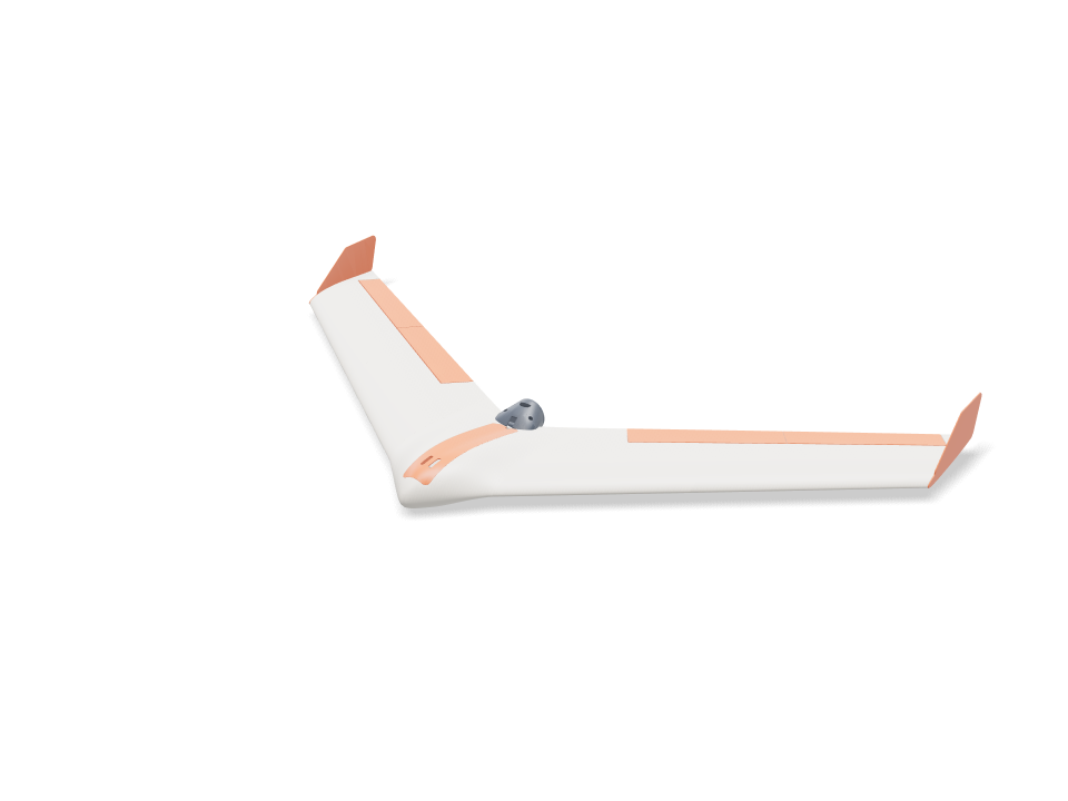
Personne ne l’a dessinée. Nous avons donné à Loftsmith une seule phrase, "A 3D printable RC flying wing" (une aile volante RC imprimable en 3D), sans dimensions, pièces ni matériel, et il a planifié l’appareil en sept étapes puis l’a construit seul : une aile propulsive de 1 m, en flèche de 37°, imprimée entièrement en PLA sur une Bambu Lab A1 et dimensionnée pour le kit de débutant classique (moteur 2212, contrôleur 30 A, LiPo 3S 2200 et deux servos MG90S). La nacelle centrale loge la batterie sous une trappe magnétique affleurante ; chaque côté compte deux panneaux d’aile imprimés debout sur leur face d’emplanture, avec des peaux de 0,8 mm sur des voiles internes, montés sur un longeron carbone de 8 mm et des clés de 6 mm avec 2° de vrillage. Les élevons débattent de ±15° sur des charnières CA, actionnés par des servos couchés à plat dans les panneaux intérieurs, et le moteur est logé dans une nacelle derrière le bord de fuite. Ce que vous voyez ici est exactement ce qu’il a produit, sans retouche, y compris ses propres remarques honnêtes : elle est lourde pour sa taille et demande du lest dans le nez pour être centrée. Pour notre aile peaufinée à la main, voyez le générateur d’aile volante RC.
Conçu par Loftsmith à partir d’un seul prompt
“A 3D printable RC flying wing”
Voici exactement ce que Loftsmith a conçu à partir du prompt ci-dessous, sans retouche : il a planifié le projet, écrit et reconstruit le modèle au fil des vérifications, et l’a terminé seul.
- Tours de conception
- 22
- Constructions (14 réussies)
- 19
- Tokens (entrée / sortie)
- 3.23M / 0.52M
- Crédits Loftsmith
- 271
- Vérifications techniques réussies
- 68
Conçu le 2026-09-28. Aux tarifs du forfait Pro, 271 crédits reviennent à environ 54 $.
Ask for the sizes you want to tweak, e.g. “make the width adjustable”.
Caractéristiques à la taille par défaut
Mesuré sur la génération réelle, sur une Bambu Lab A1 en PLA. Chaque chiffre se met à jour en direct quand vous bougez un curseur plus haut.
- Encombrement
- 1003 × 553 × 85 mm
- Pièces
- 18
- Filament
- 677 g
- Temps d’impression
- 19 h 19 min
- Plateaux
- 6
- Supports
- Aucun
Vérifications d’ingénierie
Les noms des vérifications et des paramètres viennent du moteur de CAO et sont affichés en anglais.
- Battery reaches the balance pointbalance at 20.0 % MAC = 212 mm behind the root LE needs the battery centre at y 68; the bay slides it 65 to 96 mm
- Nose weight fits the nose tip40 g of lead (26 x 7 x 20 mm) ahead of the battery, overlap 0.0 mm³; room for 57 g
- Nose weight stays modest40 g of lead = 3.7 % of all-up weight (limit 5 %); LW-PLA wing panels are the next way to cut it
- Battery fits the bay, front and backoverlap 0.0 / 0.0 mm³; 31 mm of slide, loads straight down through a 40 mm wide opening
- ESC and receiver fit their side baysoverlap 0.0 / 0.0 mm³; they slide in sideways under the skin, before the battery
- Spar tunnel stays inside the joint face1.6 mm of PLA above and below the 8 mm tube at the panel joint (75 % chord)
- Wing loading1083 g all-up on 18.6 dm² = 58 g/dm²; stall about 11.5 m/s (CL 0.7). Limit 60 g/dm² and a stall under 12 m/s for a firm hand launch; the plan's 35 g/dm² is not reachable with 0.8 mm PLA skins
- Enough thrust to hand launchabout 800 g static thrust (estimate) for 1083 g all-up = 0.74 : 1 (want 0.6+)
- Carbon spar at the panel root (4 g pull-up)80 MPa in an 8x6 mm carbon tube (allow ~250 MPa)
- Joiner at the panel joint (4 g pull-up)57 MPa in a 6x4 mm carbon tube (allow ~250 MPa); the glued PLA joint face shares the load
- Spar and joiner buried in the wing1.2 mm of PLA round the 8 mm spar out to 230 mm (100.0 % inside) and round the 6 mm joiner, 60 mm into each panel (100.0 %)
- Spar and joiner don't clashthe 8 mm spar stops 40 mm short of the panel joint on its own shear web; the joiner rides the 40 % chord web behind it
- Anti-twist pins buried at both joints3 mm carbon pins, 11 mm into each face, bosses 100.0 % inside the skin
- Internal webs print without supportdiagonal webs lean at most 27° from vertical with the panel standing on its root
- Wing inner panel fits the A1 bed190 mm tall standing on its root; 274 x 21 mm footprint needs 209 mm turned 45°
- Wing inner panel stands steady while printingits centre of mass (y 210) sits 59 mm inside the root face (y 60 to 269); print with a 5 mm brim
- Wing outer panel fits the A1 bed230 mm tall standing on its root; 323 x 19 mm footprint needs 242 mm turned 45°
- Wing outer panel stands steady while printingits centre of mass (y 358) sits 28 mm inside the root face (y 203 to 386); print with a 5 mm brim
- Fits the A1 bed standing on its side160 mm tall; 282 x 51 mm footprint needs 236 mm turned 45°
- Centre filament target153 g of PLA (target 170 g)
- Wing panel filament target361 g of PLA for all four panels (target 400 g)
- Elevon sizeabout 3.30 dm² = 18 % of the wing (aim 12-25 %), 28 % of the local chord
- Elevons swing ±15° clear of the wingtightest gap at the hinge face 0.9 mm (V below and Λ above the hinge line at 22°); ends cut square to the hinge with 0.8 mm gaps
- Hinge pockets stay under the skin1.0 mm of top skin over the thinnest end of the strip pockets
- Hinge strip flex0.8 mm bought CA hinge bends over 3.6 mm of free length: 2.9 % surface strain at 15° (keep under ~10 % for long life)
- Elevon halves fit the A1 bed on end201 / 201 mm tall standing on their square ends
- Elevon joint pin buried3 mm carbon pin, 11 mm into each half; boss 100.0 % inside the skin
- Servo fits the wing depthMG90S lying flat: 1.4 mm of top skin over the pocket, 1.1 mm above the cover plate
- Servo pocket clear of spar and joinerpocket walls vs spar / joiner sleeves: 0.00 / 0.00 mm³
- Servo travel for ±15° elevonservo horn hole 12.3 mm from the shaft, control horn hole 15.1 mm below the hinge: ±15° needs ±19° of servo
- Servo torque (estimate)about 4.9 N·cm at 22 m/s full throw (hinge-moment coefficient 0.25 assumed) vs ~18 N·cm MG90S stall; keep under half
- Control horn at servo stall2.3 MPa at the horn root with 15 N on the pushrod (servo stalled), along the layers; allow 16.7
- Control horn swings clear of the wingoverlap at +15 / 0 / -15°: 0.0 / 0.0 / 0.2 mm³
- Pushrod runs clear74 mm pushrod under the skin; 0.00 mm³ overlap with the wing, cover, elevon and horn
- Servo lead channel stays inside the skin11 x 6 mm channel for the 15 x 8 x 4.2 mm plug, 135 mm long: 100.0 % inside with its 0.8 mm walls
- Servo cover sits flushthe flat plate stands up to 0.7 mm proud of the curved skin at its edges
- Servo and cover are fastenedservo: 2 tab screws 6 mm into the cover lugs; cover: 2x M2 into heat-set inserts with 1.6 mm boss wall
- Prop clears the trailing edgeblade tips run 5.0 mm behind the swept trailing edge at 102 mm radius; swept disc overlaps the airframe by 0.0 mm³
- Spar covered where the tail thins100.0 % of a 1.2 mm skin round the 8 mm spar is enclosed across the middle 64 mm, with the pod fitted
- Pod bolts clamp solid PLAthe centre tail is 100 % solid round each M3 bolt, so clamping cannot crush a hollow skin
- Pod carries the motor on a hard landing0.14 MPa across the layers of the 1.2 mm PLA shell at a 10 g landing (motor + prop on a 43 mm arm); allow 5.0
- Prop parked clear on landingwith the ESC brake set the prop stops level; its hub bottom sits 15 mm above the pod belly, which touches down first
- Motor and plate are fastenedmotor: 4x M3x6 through the plate into its 16x19 holes; plate: 3x M3x8 into heat-set inserts, 5.3 mm from the plate edge (need 5.1), heads 0.3 mm clear of the motor can
- Pod filament target26 g of PLA for the pod and plate (target 40 g)
- Winglet size (yaw stability)two winglets add 1.14 dm² = 6.1 % of the wing area (aim 6-9 %)
- Winglet pegs keyed into a solid tip2x 4 mm square pegs, 7 mm deep, 0.15 mm glue gap; 4.3 mm of tip above and below each pocket; bosses 99.9 % inside the skin
- Winglet root in a side gust1.4 MPa where the plate leaves the tip (1.7 N side load at 22 m/s, CL 1, taken on half the tip chord), along the layers; allow 16.7
- Winglet filament target14.7 g of PLA each (target 16 g)
- Winglet fits the A1 bed163 x 68 mm lying on its outer face
- Hatch sits flush without clashinghatch vs centre overlap 0.05 mm³; top cut from the pod surface, 0.2 mm gap all round, resting on 2.5 mm side ledges and the rear bulkhead; 17 g
- Hatch stays on in flightsuction about 2.3 N at 22 m/s (pressure coefficient -1 assumed); the 6 mm front tongue takes half, two 6x3 mm magnet pairs hold ~10 N at the back
- Battery held downvelcro on the cradle ribs sets its slide position; the hatch skin or its keeper rails sit 1.2-1.5 mm above the battery along its whole length (a 2 mm foam strip on the rails takes up the play)
- Motor wires pass to the pod5.7 mm tall x 8 mm wide gap between the magnet pads, over the bulkhead and out the 7 mm rear notch into the pod slot: room for three 16 AWG leads
- Magnet pockets stay inside the bulkhead3.8 mm of PLA under each 6x3 mm magnet pocket
- battery 3S 2200 goes in25 poses along its path clear of every part.
- ESC 30 A goes in42 poses along its path clear of every part.
- receiver goes in41 poses along its path clear of every part.
- nose weight (lead) goes in36 poses along its path clear of every part.
- servo MG90S R goes in23 poses along its path clear of every part.
- servo MG90S L goes in23 poses along its path clear of every part.
- servo plug R goes in60 poses along its path clear of every part.
- servo plug L goes in60 poses along its path clear of every part.
- driver: servo tab screw (bench) goes in15 poses along its path clear of every part.
- driver: cover screw goes in15 poses along its path clear of every part.
- motor 2212 goes in20 poses along its path clear of every part.
- motor lead (3.5 mm bullet) goes in18 poses along its path clear of every part.
- driver: motor plate screw goes in15 poses along its path clear of every part.
- driver: pod bolt goes in15 poses along its path clear of every part.
Dimensions réglables
| Paramètre | Par défaut | Plage |
|---|---|---|
| Wingspan | 1000 mm | 800–1020 mm |
| Leading-edge sweep | 37 ° | 32–38 ° |
| Wing root chord | 220 mm | 190–225 mm |
| Tip chord | 150 mm | 110–170 mm |
| Centre half-width | 80 mm | 65–85 mm |
| Pod thickness | 22 % | 18–24 % |
| Balance point | 20 % MAC | 15–22 % MAC |
| Wing panel skin | 0.8 mm | 0.8–1.2 mm |
| Tip washout | 2 ° | 0–4 ° |
| Elevon chord | 28 % chord | 22–32 % chord |
| Elevon inboard end | 150 mm | 130–190 mm |
| Winglet height | 52 mm | 40–70 mm |
Liste des pièces
| Pièce | Qté | Taille (mm) | Filament | Durée |
|---|---|---|---|---|
| center-section | 1 | 204 × 203 × 160 | 152 g | 3 h 37 min |
| wing-inner-R | 1 | 200 × 197 × 190 | 95 g | 2 h 25 min |
| wing-outer-R | 1 | 233 × 227 × 230 | 86 g | 2 h 19 min |
| wing-inner-L | 1 | 197 × 200 × 190 | 95 g | 2 h 25 min |
| wing-outer-L | 1 | 227 × 233 × 230 | 86 g | 2 h 19 min |
| elevon-inner-R | 1 | 47 × 12 × 200 | 24 g | 54 min |
| elevon-outer-R | 1 | 42 × 10 × 200 | 20 g | 50 min |
| elevon-inner-L | 1 | 47 × 12 × 200 | 24 g | 54 min |
| elevon-outer-L | 1 | 42 × 10 × 200 | 20 g | 50 min |
| servo-cover-R | 1 | 63 × 51 × 15 | 3 g | 10 min |
| servo-cover-L | 1 | 63 × 51 × 15 | 3 g | 10 min |
| control-horn-R | 1 | 20 × 13 × 2 | 0 g | 5 min |
| control-horn-L | 1 | 20 × 13 × 2 | 0 g | 5 min |
| motor-mount | 1 | 62 × 45 × 45 | 19 g | 33 min |
| motor-plate | 1 | 45 × 45 × 3 | 4 g | 9 min |
| winglet-R | 1 | 68 × 163 × 9 | 15 g | 24 min |
| winglet-L | 1 | 68 × 163 × 9 | 15 g | 24 min |
| hatch | 1 | 40 × 27 × 203 | 17 g | 46 min |
Comment la réaliser
- Imprimez d’abord la section centrale et vérifiez l’ajustement du longeron, de la batterie et de la trappe.
- Collez les tétons d’emplanture à l’époxy, glissez la nacelle moteur sur l’arrière, puis enfilez le longeron de 8 mm dans le centre et les deux panneaux intérieurs et collez les faces d’emplanture.
- Collez les clés de 6 mm et les tétons extérieurs dans les panneaux intérieurs, puis glissez les panneaux extérieurs le long des clés et collez-les.
- Collez les deux moitiés de chaque élevon sur un téton de 3 mm. Insérez les charnières CA dans les logements de l’aile et de l’élevon, vérifiez le débattement de ±15°, puis faites pénétrer de la cyano fluide.
- Vissez chaque servo sur son capot à l’établi, faites passer le câble par le canal jusqu’à la baie, puis fixez le capot avec 2x M2x6. Collez les guignols dans les fentes des élevons et montez les tringles pliées en Z.
- Vissez le moteur sur sa platine, fixez la nacelle avec 2x M3x12, montez la platine avec 3x M3x8, collez les winglets par leurs tétons, puis réglez le centrage avec la batterie et du lest dans le nez avant le premier vol.
Conseils d’impression
- Toutes les pièces en PLA à 0,2 mm, 2 parois et 15 % de remplissage, sans supports.
- Ajoutez une bordure (brim) de 5 mm sur les pièces hautes et ralentissez les parois extérieures des panneaux d’aile ; des bords de fuite fins sont normaux.
- La nacelle moteur en PLA ramollit vers 55 °C : si le moteur est trop chaud pour être tenu après un vol, réimprimez la nacelle et la platine en PETG.
FAQ
A-t-elle vraiment été faite à partir d’un seul prompt ?
Oui. La seule entrée était "A 3D printable RC flying wing" (une aile volante RC imprimable en 3D), avec une Bambu Lab A1 et du PLA sélectionnés. Loftsmith a planifié sept étapes, écrit et reconstruit le modèle 19 fois au fil des retours des vérifications techniques, puis l’a finalisé. Le modèle et les remarques de cette page sont sa production brute, sans retouche.
Combien a coûté la conception ?
22 tours de conception, 3,2 millions de tokens en entrée et 0,52 million en sortie : 271 crédits Loftsmith, soit environ 54 $ aux tarifs du forfait Pro. C’est précisément pour un gros projet comme celui-ci qu’existe le pack de crédits Gros projet.
Est-ce qu’elle volera ?
Elle est conçue pour, et toutes les vérifications techniques passent, mais elle n’a pas été testée en vol et elle est lourde pour sa taille (environ 58 g/dm²) : il lui faut à peu près 40 g de lest dans le nez et un lancer main ferme. Vérifiez d’abord le centrage et le débattement des élevons à la main.
Comments