Un'ala volante RC progettata da Loftsmith con un solo prompt
Nessuno l'ha disegnata. Abbiamo dato a Loftsmith una sola frase, "A 3D printable RC flying wing" (un'ala volante RC stampabile in 3D), senza misure, pezzi o hardware, e ha pianificato l'aereo in sette fasi e l'ha costruito da solo: un'ala spingente da 1 m con freccia di 37°, stampata interamente in PLA su una Bambu Lab A1 e dimensionata per il classico kit da principiante (motore 2212, ESC da 30 A, LiPo 3S 2200 e due servo MG90S). La gondola centrale ospita la batteria sotto un portello magnetico a filo; ogni lato ha due pannelli alari stampati in piedi sulla faccia di radice, con gusci da 0,8 mm su anime interne, montati su un longherone in carbonio da 8 mm e giunti da 6 mm con 2° di svergolamento. Gli elevoni hanno un'escursione di ±15° su cerniere CA, mossi da servo sdraiati nei pannelli interni, e il motore sta in una gondola dietro il bordo d'uscita. Quello che vedi qui è esattamente ciò che ha prodotto, senza modifiche, comprese le sue note oneste: è pesante per le sue dimensioni e serve zavorra sul muso per centrarla. Per la nostra ala rifinita a mano, guarda il generatore di ala volante RC.
Creato da Loftsmith con un solo prompt
“A 3D printable RC flying wing”
Questo è esattamente ciò che Loftsmith ha progettato dal prompt qui sotto, senza modifiche: ha pianificato il progetto, scritto e ricostruito il modello man mano che arrivavano le verifiche, e l'ha completato da solo.
- Turni di progettazione
- 22
- Build (14 riuscite)
- 19
- Token (input / output)
- 3.23M / 0.52M
- Crediti Loftsmith
- 271
- Verifiche ingegneristiche superate
- 68
Progettato il 2026-09-28. Ai prezzi del piano Pro, 271 crediti corrispondono a circa 54 $.
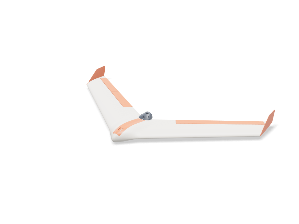
Ask for the sizes you want to tweak, e.g. “make the width adjustable”.
Specifiche alla dimensione predefinita
Misurate sulla generazione reale su una Bambu Lab A1 in PLA. Ogni numero si aggiorna in tempo reale quando trascini un cursore qui sopra.
- Ingombro
- 1003 × 553 × 85 mm
- Pezzi
- 18
- Filamento
- 677 g
- Tempo di stampa
- 19 h 19 min
- Piatti
- 6
- Supporti
- Non servono
Controlli ingegneristici
I nomi dei controlli e dei parametri arrivano dal motore CAD e sono mostrati in inglese.
- Battery reaches the balance pointbalance at 20.0 % MAC = 212 mm behind the root LE needs the battery centre at y 68; the bay slides it 65 to 96 mm
- Nose weight fits the nose tip40 g of lead (26 x 7 x 20 mm) ahead of the battery, overlap 0.0 mm³; room for 57 g
- Nose weight stays modest40 g of lead = 3.7 % of all-up weight (limit 5 %); LW-PLA wing panels are the next way to cut it
- Battery fits the bay, front and backoverlap 0.0 / 0.0 mm³; 31 mm of slide, loads straight down through a 40 mm wide opening
- ESC and receiver fit their side baysoverlap 0.0 / 0.0 mm³; they slide in sideways under the skin, before the battery
- Spar tunnel stays inside the joint face1.6 mm of PLA above and below the 8 mm tube at the panel joint (75 % chord)
- Wing loading1083 g all-up on 18.6 dm² = 58 g/dm²; stall about 11.5 m/s (CL 0.7). Limit 60 g/dm² and a stall under 12 m/s for a firm hand launch; the plan's 35 g/dm² is not reachable with 0.8 mm PLA skins
- Enough thrust to hand launchabout 800 g static thrust (estimate) for 1083 g all-up = 0.74 : 1 (want 0.6+)
- Carbon spar at the panel root (4 g pull-up)80 MPa in an 8x6 mm carbon tube (allow ~250 MPa)
- Joiner at the panel joint (4 g pull-up)57 MPa in a 6x4 mm carbon tube (allow ~250 MPa); the glued PLA joint face shares the load
- Spar and joiner buried in the wing1.2 mm of PLA round the 8 mm spar out to 230 mm (100.0 % inside) and round the 6 mm joiner, 60 mm into each panel (100.0 %)
- Spar and joiner don't clashthe 8 mm spar stops 40 mm short of the panel joint on its own shear web; the joiner rides the 40 % chord web behind it
- Anti-twist pins buried at both joints3 mm carbon pins, 11 mm into each face, bosses 100.0 % inside the skin
- Internal webs print without supportdiagonal webs lean at most 27° from vertical with the panel standing on its root
- Wing inner panel fits the A1 bed190 mm tall standing on its root; 274 x 21 mm footprint needs 209 mm turned 45°
- Wing inner panel stands steady while printingits centre of mass (y 210) sits 59 mm inside the root face (y 60 to 269); print with a 5 mm brim
- Wing outer panel fits the A1 bed230 mm tall standing on its root; 323 x 19 mm footprint needs 242 mm turned 45°
- Wing outer panel stands steady while printingits centre of mass (y 358) sits 28 mm inside the root face (y 203 to 386); print with a 5 mm brim
- Fits the A1 bed standing on its side160 mm tall; 282 x 51 mm footprint needs 236 mm turned 45°
- Centre filament target153 g of PLA (target 170 g)
- Wing panel filament target361 g of PLA for all four panels (target 400 g)
- Elevon sizeabout 3.30 dm² = 18 % of the wing (aim 12-25 %), 28 % of the local chord
- Elevons swing ±15° clear of the wingtightest gap at the hinge face 0.9 mm (V below and Λ above the hinge line at 22°); ends cut square to the hinge with 0.8 mm gaps
- Hinge pockets stay under the skin1.0 mm of top skin over the thinnest end of the strip pockets
- Hinge strip flex0.8 mm bought CA hinge bends over 3.6 mm of free length: 2.9 % surface strain at 15° (keep under ~10 % for long life)
- Elevon halves fit the A1 bed on end201 / 201 mm tall standing on their square ends
- Elevon joint pin buried3 mm carbon pin, 11 mm into each half; boss 100.0 % inside the skin
- Servo fits the wing depthMG90S lying flat: 1.4 mm of top skin over the pocket, 1.1 mm above the cover plate
- Servo pocket clear of spar and joinerpocket walls vs spar / joiner sleeves: 0.00 / 0.00 mm³
- Servo travel for ±15° elevonservo horn hole 12.3 mm from the shaft, control horn hole 15.1 mm below the hinge: ±15° needs ±19° of servo
- Servo torque (estimate)about 4.9 N·cm at 22 m/s full throw (hinge-moment coefficient 0.25 assumed) vs ~18 N·cm MG90S stall; keep under half
- Control horn at servo stall2.3 MPa at the horn root with 15 N on the pushrod (servo stalled), along the layers; allow 16.7
- Control horn swings clear of the wingoverlap at +15 / 0 / -15°: 0.0 / 0.0 / 0.2 mm³
- Pushrod runs clear74 mm pushrod under the skin; 0.00 mm³ overlap with the wing, cover, elevon and horn
- Servo lead channel stays inside the skin11 x 6 mm channel for the 15 x 8 x 4.2 mm plug, 135 mm long: 100.0 % inside with its 0.8 mm walls
- Servo cover sits flushthe flat plate stands up to 0.7 mm proud of the curved skin at its edges
- Servo and cover are fastenedservo: 2 tab screws 6 mm into the cover lugs; cover: 2x M2 into heat-set inserts with 1.6 mm boss wall
- Prop clears the trailing edgeblade tips run 5.0 mm behind the swept trailing edge at 102 mm radius; swept disc overlaps the airframe by 0.0 mm³
- Spar covered where the tail thins100.0 % of a 1.2 mm skin round the 8 mm spar is enclosed across the middle 64 mm, with the pod fitted
- Pod bolts clamp solid PLAthe centre tail is 100 % solid round each M3 bolt, so clamping cannot crush a hollow skin
- Pod carries the motor on a hard landing0.14 MPa across the layers of the 1.2 mm PLA shell at a 10 g landing (motor + prop on a 43 mm arm); allow 5.0
- Prop parked clear on landingwith the ESC brake set the prop stops level; its hub bottom sits 15 mm above the pod belly, which touches down first
- Motor and plate are fastenedmotor: 4x M3x6 through the plate into its 16x19 holes; plate: 3x M3x8 into heat-set inserts, 5.3 mm from the plate edge (need 5.1), heads 0.3 mm clear of the motor can
- Pod filament target26 g of PLA for the pod and plate (target 40 g)
- Winglet size (yaw stability)two winglets add 1.14 dm² = 6.1 % of the wing area (aim 6-9 %)
- Winglet pegs keyed into a solid tip2x 4 mm square pegs, 7 mm deep, 0.15 mm glue gap; 4.3 mm of tip above and below each pocket; bosses 99.9 % inside the skin
- Winglet root in a side gust1.4 MPa where the plate leaves the tip (1.7 N side load at 22 m/s, CL 1, taken on half the tip chord), along the layers; allow 16.7
- Winglet filament target14.7 g of PLA each (target 16 g)
- Winglet fits the A1 bed163 x 68 mm lying on its outer face
- Hatch sits flush without clashinghatch vs centre overlap 0.05 mm³; top cut from the pod surface, 0.2 mm gap all round, resting on 2.5 mm side ledges and the rear bulkhead; 17 g
- Hatch stays on in flightsuction about 2.3 N at 22 m/s (pressure coefficient -1 assumed); the 6 mm front tongue takes half, two 6x3 mm magnet pairs hold ~10 N at the back
- Battery held downvelcro on the cradle ribs sets its slide position; the hatch skin or its keeper rails sit 1.2-1.5 mm above the battery along its whole length (a 2 mm foam strip on the rails takes up the play)
- Motor wires pass to the pod5.7 mm tall x 8 mm wide gap between the magnet pads, over the bulkhead and out the 7 mm rear notch into the pod slot: room for three 16 AWG leads
- Magnet pockets stay inside the bulkhead3.8 mm of PLA under each 6x3 mm magnet pocket
- battery 3S 2200 goes in25 poses along its path clear of every part.
- ESC 30 A goes in42 poses along its path clear of every part.
- receiver goes in41 poses along its path clear of every part.
- nose weight (lead) goes in36 poses along its path clear of every part.
- servo MG90S R goes in23 poses along its path clear of every part.
- servo MG90S L goes in23 poses along its path clear of every part.
- servo plug R goes in60 poses along its path clear of every part.
- servo plug L goes in60 poses along its path clear of every part.
- driver: servo tab screw (bench) goes in15 poses along its path clear of every part.
- driver: cover screw goes in15 poses along its path clear of every part.
- motor 2212 goes in20 poses along its path clear of every part.
- motor lead (3.5 mm bullet) goes in18 poses along its path clear of every part.
- driver: motor plate screw goes in15 poses along its path clear of every part.
- driver: pod bolt goes in15 poses along its path clear of every part.
Misure regolabili
| Parametro | Predefinito | Intervallo |
|---|---|---|
| Wingspan | 1000 mm | 800–1020 mm |
| Leading-edge sweep | 37 ° | 32–38 ° |
| Wing root chord | 220 mm | 190–225 mm |
| Tip chord | 150 mm | 110–170 mm |
| Centre half-width | 80 mm | 65–85 mm |
| Pod thickness | 22 % | 18–24 % |
| Balance point | 20 % MAC | 15–22 % MAC |
| Wing panel skin | 0.8 mm | 0.8–1.2 mm |
| Tip washout | 2 ° | 0–4 ° |
| Elevon chord | 28 % chord | 22–32 % chord |
| Elevon inboard end | 150 mm | 130–190 mm |
| Winglet height | 52 mm | 40–70 mm |
Distinta dei pezzi
| Pezzo | Q.tà | Dimensioni (mm) | Filamento | Tempo |
|---|---|---|---|---|
| center-section | 1 | 204 × 203 × 160 | 152 g | 3 h 37 min |
| wing-inner-R | 1 | 200 × 197 × 190 | 95 g | 2 h 25 min |
| wing-outer-R | 1 | 233 × 227 × 230 | 86 g | 2 h 19 min |
| wing-inner-L | 1 | 197 × 200 × 190 | 95 g | 2 h 25 min |
| wing-outer-L | 1 | 227 × 233 × 230 | 86 g | 2 h 19 min |
| elevon-inner-R | 1 | 47 × 12 × 200 | 24 g | 54 min |
| elevon-outer-R | 1 | 42 × 10 × 200 | 20 g | 50 min |
| elevon-inner-L | 1 | 47 × 12 × 200 | 24 g | 54 min |
| elevon-outer-L | 1 | 42 × 10 × 200 | 20 g | 50 min |
| servo-cover-R | 1 | 63 × 51 × 15 | 3 g | 10 min |
| servo-cover-L | 1 | 63 × 51 × 15 | 3 g | 10 min |
| control-horn-R | 1 | 20 × 13 × 2 | 0 g | 5 min |
| control-horn-L | 1 | 20 × 13 × 2 | 0 g | 5 min |
| motor-mount | 1 | 62 × 45 × 45 | 19 g | 33 min |
| motor-plate | 1 | 45 × 45 × 3 | 4 g | 9 min |
| winglet-R | 1 | 68 × 163 × 9 | 15 g | 24 min |
| winglet-L | 1 | 68 × 163 × 9 | 15 g | 24 min |
| hatch | 1 | 40 × 27 × 203 | 17 g | 46 min |
Come realizzarlo
- Stampa prima la sezione centrale e prova l'accoppiamento di longherone, batteria e portello.
- Incolla con epossidica i perni di radice, infila la gondola motore sulla coda, poi fai passare il longherone da 8 mm nel centro e nei due pannelli interni e incolla le facce di radice.
- Incolla i giunti da 6 mm e i perni esterni nei pannelli interni, poi fai scorrere i pannelli esterni lungo i giunti e incollali.
- Incolla le due metà di ogni elevone su un perno da 3 mm. Inserisci le cerniere CA nelle tasche di ala ed elevone, verifica l'escursione di ±15°, poi fai penetrare del ciano fluido.
- Avvita ogni servo al suo coperchio sul banco, fai passare il cavo nel canale fino al vano, poi fissa il coperchio con 2x M2x6. Incolla le squadrette nelle fessure degli elevoni e monta i rinvii piegati a Z.
- Avvita il motore alla sua piastra, fissa la gondola con 2x M3x12, monta la piastra con 3x M3x8, incolla le winglet con i loro perni, poi regola il baricentro con la batteria e la zavorra sul muso prima del primo volo.
Consigli di stampa
- Tutti i pezzi in PLA a 0,2 mm, 2 pareti e 15% di riempimento, senza supporti.
- Aggiungi un brim da 5 mm sui pezzi alti e rallenta le pareti esterne dei pannelli alari; i bordi d'uscita sottili sono normali.
- La gondola motore in PLA si ammorbidisce intorno ai 55 °C: se dopo un volo il motore scotta troppo per tenerlo in mano, ristampa gondola e piastra in PETG.
Domande frequenti
È stata davvero fatta con un solo prompt?
Sì. L'unico input era "A 3D printable RC flying wing" (un'ala volante RC stampabile in 3D), con una Bambu Lab A1 e il PLA selezionati. Loftsmith ha pianificato sette fasi, ha scritto e ricostruito il modello 19 volte man mano che arrivavano le verifiche ingegneristiche e l'ha finalizzato. Il modello e le note in questa pagina sono il suo output, senza modifiche.
Quanto è costato progettarla?
22 turni di progettazione, 3,2 milioni di token in input e 0,52 milioni in output: 271 crediti Loftsmith, circa 54 $ ai prezzi del piano Pro. Un progetto grande come questo è proprio ciò per cui esiste il pacchetto di crediti Grande progetto.
Volerà?
È progettata per farlo e supera ogni verifica ingegneristica, ma non è stata collaudata in volo ed è pesante per le sue dimensioni (circa 58 g/dm²), quindi servono circa 40 g di zavorra sul muso e un lancio a mano deciso. Controlla prima a mano il baricentro e l'escursione degli elevoni.
Comments