Loftsmith가 프롬프트 하나로 설계한 RC 비행익
아무도 그리지 않았어요. Loftsmith에게 "A 3D printable RC flying wing"(3D 프린팅 가능한 RC 비행익)라는 한 문장만 줬어요. 크기도, 부품도, 하드웨어도 정하지 않았죠. Loftsmith는 기체를 7단계로 계획하고 스스로 만들었어요. 결과는 1m 스팬에 37° 후퇴각을 준 푸셔 비행익으로, Bambu Lab A1에서 전부 PLA로 출력하고, 흔한 입문 키트(2212 모터, 30A ESC, 3S 2200 LiPo, MG90S 서보 두 개)에 맞춰 크기를 정했어요. 중앙 포드는 표면과 높이가 맞는 자석식 해치 아래에 배터리를 담아요. 양쪽에는 날개 패널이 두 장씩 있는데, 루트 면을 바닥에 세워 출력하고 내부 웹 위에 0.8mm 외피를 씌운 구조이며, 8mm 카본 스파와 2° 워시아웃을 준 6mm 조이너에 끼워져요. 엘레본은 CA 힌지로 ±15° 움직이고, 안쪽 패널에 눕혀 넣은 서보가 구동해요. 모터는 뒷전 뒤쪽 포드에 들어가요. 여기 보이는 건 Loftsmith가 만든 그대로, 손대지 않은 결과물이고 스스로 남긴 솔직한 메모도 포함돼 있어요. 크기에 비해 무겁고, 무게중심을 맞추려면 기수에 무게추가 필요해요. 저희가 손으로 다듬은 날개는 RC 비행익 생성기에서 보세요.
Loftsmith가 프롬프트 하나로 만들었어요
“A 3D printable RC flying wing”
아래 프롬프트로 Loftsmith가 설계한 결과를 손대지 않고 그대로 보여 드려요. 제작을 계획하고, 검사 결과가 돌아올 때마다 모델을 작성하고 다시 빌드하며 스스로 완성했어요.
- 설계 턴
- 22
- 빌드 (14회 통과)
- 19
- 토큰 (입력 / 출력)
- 3.23M / 0.52M
- Loftsmith 크레딧
- 271
- 통과한 엔지니어링 검사
- 68
2026-09-28에 설계. Pro 플랜 가격 기준으로 271 크레딧은 약 54달러예요.
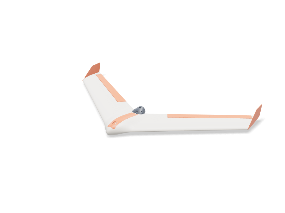
Ask for the sizes you want to tweak, e.g. “make the width adjustable”.
기본 크기 사양
Bambu Lab A1에서 PLA로 실제 빌드해 측정했어요. 위 슬라이더를 움직이면 모든 숫자가 실시간으로 바뀌어요.
- 전체 크기
- 1003 × 553 × 85 mm
- 부품 수
- 18
- 필라멘트
- 677 g
- 출력 시간
- 19 h 19 min
- 빌드 플레이트
- 6
- 서포트
- 필요 없음
공학 검사
검사 이름과 파라미터 이름은 CAD 엔진에서 그대로 나오기 때문에 영어로 표시돼요.
- Battery reaches the balance pointbalance at 20.0 % MAC = 212 mm behind the root LE needs the battery centre at y 68; the bay slides it 65 to 96 mm
- Nose weight fits the nose tip40 g of lead (26 x 7 x 20 mm) ahead of the battery, overlap 0.0 mm³; room for 57 g
- Nose weight stays modest40 g of lead = 3.7 % of all-up weight (limit 5 %); LW-PLA wing panels are the next way to cut it
- Battery fits the bay, front and backoverlap 0.0 / 0.0 mm³; 31 mm of slide, loads straight down through a 40 mm wide opening
- ESC and receiver fit their side baysoverlap 0.0 / 0.0 mm³; they slide in sideways under the skin, before the battery
- Spar tunnel stays inside the joint face1.6 mm of PLA above and below the 8 mm tube at the panel joint (75 % chord)
- Wing loading1083 g all-up on 18.6 dm² = 58 g/dm²; stall about 11.5 m/s (CL 0.7). Limit 60 g/dm² and a stall under 12 m/s for a firm hand launch; the plan's 35 g/dm² is not reachable with 0.8 mm PLA skins
- Enough thrust to hand launchabout 800 g static thrust (estimate) for 1083 g all-up = 0.74 : 1 (want 0.6+)
- Carbon spar at the panel root (4 g pull-up)80 MPa in an 8x6 mm carbon tube (allow ~250 MPa)
- Joiner at the panel joint (4 g pull-up)57 MPa in a 6x4 mm carbon tube (allow ~250 MPa); the glued PLA joint face shares the load
- Spar and joiner buried in the wing1.2 mm of PLA round the 8 mm spar out to 230 mm (100.0 % inside) and round the 6 mm joiner, 60 mm into each panel (100.0 %)
- Spar and joiner don't clashthe 8 mm spar stops 40 mm short of the panel joint on its own shear web; the joiner rides the 40 % chord web behind it
- Anti-twist pins buried at both joints3 mm carbon pins, 11 mm into each face, bosses 100.0 % inside the skin
- Internal webs print without supportdiagonal webs lean at most 27° from vertical with the panel standing on its root
- Wing inner panel fits the A1 bed190 mm tall standing on its root; 274 x 21 mm footprint needs 209 mm turned 45°
- Wing inner panel stands steady while printingits centre of mass (y 210) sits 59 mm inside the root face (y 60 to 269); print with a 5 mm brim
- Wing outer panel fits the A1 bed230 mm tall standing on its root; 323 x 19 mm footprint needs 242 mm turned 45°
- Wing outer panel stands steady while printingits centre of mass (y 358) sits 28 mm inside the root face (y 203 to 386); print with a 5 mm brim
- Fits the A1 bed standing on its side160 mm tall; 282 x 51 mm footprint needs 236 mm turned 45°
- Centre filament target153 g of PLA (target 170 g)
- Wing panel filament target361 g of PLA for all four panels (target 400 g)
- Elevon sizeabout 3.30 dm² = 18 % of the wing (aim 12-25 %), 28 % of the local chord
- Elevons swing ±15° clear of the wingtightest gap at the hinge face 0.9 mm (V below and Λ above the hinge line at 22°); ends cut square to the hinge with 0.8 mm gaps
- Hinge pockets stay under the skin1.0 mm of top skin over the thinnest end of the strip pockets
- Hinge strip flex0.8 mm bought CA hinge bends over 3.6 mm of free length: 2.9 % surface strain at 15° (keep under ~10 % for long life)
- Elevon halves fit the A1 bed on end201 / 201 mm tall standing on their square ends
- Elevon joint pin buried3 mm carbon pin, 11 mm into each half; boss 100.0 % inside the skin
- Servo fits the wing depthMG90S lying flat: 1.4 mm of top skin over the pocket, 1.1 mm above the cover plate
- Servo pocket clear of spar and joinerpocket walls vs spar / joiner sleeves: 0.00 / 0.00 mm³
- Servo travel for ±15° elevonservo horn hole 12.3 mm from the shaft, control horn hole 15.1 mm below the hinge: ±15° needs ±19° of servo
- Servo torque (estimate)about 4.9 N·cm at 22 m/s full throw (hinge-moment coefficient 0.25 assumed) vs ~18 N·cm MG90S stall; keep under half
- Control horn at servo stall2.3 MPa at the horn root with 15 N on the pushrod (servo stalled), along the layers; allow 16.7
- Control horn swings clear of the wingoverlap at +15 / 0 / -15°: 0.0 / 0.0 / 0.2 mm³
- Pushrod runs clear74 mm pushrod under the skin; 0.00 mm³ overlap with the wing, cover, elevon and horn
- Servo lead channel stays inside the skin11 x 6 mm channel for the 15 x 8 x 4.2 mm plug, 135 mm long: 100.0 % inside with its 0.8 mm walls
- Servo cover sits flushthe flat plate stands up to 0.7 mm proud of the curved skin at its edges
- Servo and cover are fastenedservo: 2 tab screws 6 mm into the cover lugs; cover: 2x M2 into heat-set inserts with 1.6 mm boss wall
- Prop clears the trailing edgeblade tips run 5.0 mm behind the swept trailing edge at 102 mm radius; swept disc overlaps the airframe by 0.0 mm³
- Spar covered where the tail thins100.0 % of a 1.2 mm skin round the 8 mm spar is enclosed across the middle 64 mm, with the pod fitted
- Pod bolts clamp solid PLAthe centre tail is 100 % solid round each M3 bolt, so clamping cannot crush a hollow skin
- Pod carries the motor on a hard landing0.14 MPa across the layers of the 1.2 mm PLA shell at a 10 g landing (motor + prop on a 43 mm arm); allow 5.0
- Prop parked clear on landingwith the ESC brake set the prop stops level; its hub bottom sits 15 mm above the pod belly, which touches down first
- Motor and plate are fastenedmotor: 4x M3x6 through the plate into its 16x19 holes; plate: 3x M3x8 into heat-set inserts, 5.3 mm from the plate edge (need 5.1), heads 0.3 mm clear of the motor can
- Pod filament target26 g of PLA for the pod and plate (target 40 g)
- Winglet size (yaw stability)two winglets add 1.14 dm² = 6.1 % of the wing area (aim 6-9 %)
- Winglet pegs keyed into a solid tip2x 4 mm square pegs, 7 mm deep, 0.15 mm glue gap; 4.3 mm of tip above and below each pocket; bosses 99.9 % inside the skin
- Winglet root in a side gust1.4 MPa where the plate leaves the tip (1.7 N side load at 22 m/s, CL 1, taken on half the tip chord), along the layers; allow 16.7
- Winglet filament target14.7 g of PLA each (target 16 g)
- Winglet fits the A1 bed163 x 68 mm lying on its outer face
- Hatch sits flush without clashinghatch vs centre overlap 0.05 mm³; top cut from the pod surface, 0.2 mm gap all round, resting on 2.5 mm side ledges and the rear bulkhead; 17 g
- Hatch stays on in flightsuction about 2.3 N at 22 m/s (pressure coefficient -1 assumed); the 6 mm front tongue takes half, two 6x3 mm magnet pairs hold ~10 N at the back
- Battery held downvelcro on the cradle ribs sets its slide position; the hatch skin or its keeper rails sit 1.2-1.5 mm above the battery along its whole length (a 2 mm foam strip on the rails takes up the play)
- Motor wires pass to the pod5.7 mm tall x 8 mm wide gap between the magnet pads, over the bulkhead and out the 7 mm rear notch into the pod slot: room for three 16 AWG leads
- Magnet pockets stay inside the bulkhead3.8 mm of PLA under each 6x3 mm magnet pocket
- battery 3S 2200 goes in25 poses along its path clear of every part.
- ESC 30 A goes in42 poses along its path clear of every part.
- receiver goes in41 poses along its path clear of every part.
- nose weight (lead) goes in36 poses along its path clear of every part.
- servo MG90S R goes in23 poses along its path clear of every part.
- servo MG90S L goes in23 poses along its path clear of every part.
- servo plug R goes in60 poses along its path clear of every part.
- servo plug L goes in60 poses along its path clear of every part.
- driver: servo tab screw (bench) goes in15 poses along its path clear of every part.
- driver: cover screw goes in15 poses along its path clear of every part.
- motor 2212 goes in20 poses along its path clear of every part.
- motor lead (3.5 mm bullet) goes in18 poses along its path clear of every part.
- driver: motor plate screw goes in15 poses along its path clear of every part.
- driver: pod bolt goes in15 poses along its path clear of every part.
조절 가능한 치수
| 설정 | 기본값 | 범위 |
|---|---|---|
| Wingspan | 1000 mm | 800–1020 mm |
| Leading-edge sweep | 37 ° | 32–38 ° |
| Wing root chord | 220 mm | 190–225 mm |
| Tip chord | 150 mm | 110–170 mm |
| Centre half-width | 80 mm | 65–85 mm |
| Pod thickness | 22 % | 18–24 % |
| Balance point | 20 % MAC | 15–22 % MAC |
| Wing panel skin | 0.8 mm | 0.8–1.2 mm |
| Tip washout | 2 ° | 0–4 ° |
| Elevon chord | 28 % chord | 22–32 % chord |
| Elevon inboard end | 150 mm | 130–190 mm |
| Winglet height | 52 mm | 40–70 mm |
부품 목록
| 부품 | 수량 | 크기(mm) | 필라멘트 | 시간 |
|---|---|---|---|---|
| center-section | 1 | 204 × 203 × 160 | 152 g | 3 h 37 min |
| wing-inner-R | 1 | 200 × 197 × 190 | 95 g | 2 h 25 min |
| wing-outer-R | 1 | 233 × 227 × 230 | 86 g | 2 h 19 min |
| wing-inner-L | 1 | 197 × 200 × 190 | 95 g | 2 h 25 min |
| wing-outer-L | 1 | 227 × 233 × 230 | 86 g | 2 h 19 min |
| elevon-inner-R | 1 | 47 × 12 × 200 | 24 g | 54 min |
| elevon-outer-R | 1 | 42 × 10 × 200 | 20 g | 50 min |
| elevon-inner-L | 1 | 47 × 12 × 200 | 24 g | 54 min |
| elevon-outer-L | 1 | 42 × 10 × 200 | 20 g | 50 min |
| servo-cover-R | 1 | 63 × 51 × 15 | 3 g | 10 min |
| servo-cover-L | 1 | 63 × 51 × 15 | 3 g | 10 min |
| control-horn-R | 1 | 20 × 13 × 2 | 0 g | 5 min |
| control-horn-L | 1 | 20 × 13 × 2 | 0 g | 5 min |
| motor-mount | 1 | 62 × 45 × 45 | 19 g | 33 min |
| motor-plate | 1 | 45 × 45 × 3 | 4 g | 9 min |
| winglet-R | 1 | 68 × 163 × 9 | 15 g | 24 min |
| winglet-L | 1 | 68 × 163 × 9 | 15 g | 24 min |
| hatch | 1 | 40 × 27 × 203 | 17 g | 46 min |
만드는 법
- 먼저 센터 섹션을 출력하고 스파, 배터리, 해치를 가조립해 맞춰 보세요.
- 루트 핀을 에폭시로 고정하고, 모터 포드를 꼬리 위로 밀어 끼운 다음, 8mm 스파를 센터와 양쪽 안쪽 패널에 통과시키고 루트 면을 접착하세요.
- 6mm 조이너와 바깥쪽 핀을 안쪽 패널에 접착한 뒤, 바깥쪽 패널을 조이너를 따라 밀어 끼우고 접착하세요.
- 각 엘레본의 두 반쪽을 3mm 핀에 맞춰 붙이세요. CA 힌지를 날개와 엘레본 포켓에 끼우고 ±15° 움직임을 확인한 뒤, 묽은 순간접착제를 스며들게 하세요.
- 작업대에서 각 서보를 커버에 나사로 고정하고, 리드선을 채널을 통해 베이로 넣은 뒤 커버를 2x M2x6으로 고정하세요. 컨트롤 혼을 엘레본 슬롯에 접착하고 Z자로 구부린 푸시로드를 연결하세요.
- 모터를 플레이트에 나사로 고정하고, 포드는 2x M3x12로, 플레이트는 3x M3x8로 고정한 뒤 윙렛을 페그에 맞춰 접착하세요. 첫 비행 전에 배터리와 기수 무게추로 무게중심을 맞추세요.
출력 팁
- 모든 부품은 PLA, 0.2mm, 벽 2겹, 인필 15%, 서포트 없이 출력해요.
- 키 큰 부품에는 5mm 브림을 추가하고 날개 패널의 외벽 속도를 낮추세요. 뒷전이 얇게 나오는 건 정상이에요.
- PLA 모터 포드는 55 °C 무렵부터 물러져요. 비행 후 모터가 손으로 잡기 힘들 만큼 뜨겁다면 포드와 플레이트를 PETG로 다시 출력하세요.
자주 묻는 질문
정말 프롬프트 하나로 만들었나요?
네. 입력은 "A 3D printable RC flying wing"(3D 프린팅 가능한 RC 비행익) 한 문장뿐이었고, Bambu Lab A1과 PLA를 선택해 두었어요. Loftsmith는 7단계를 계획하고, 엔지니어링 검사 결과가 돌아올 때마다 모델을 작성하고 다시 빌드하기를 19번 반복한 뒤 마무리했어요. 이 페이지의 모델과 메모는 손대지 않은 출력 그대로예요.
설계하는 데 얼마나 들었나요?
설계 턴 22회, 입력 토큰 320만 개와 출력 토큰 52만 개로, Loftsmith 크레딧 271, Pro 플랜 가격 기준 약 54달러예요. 이런 큰 작업을 위해 빅 빌드 크레딧 팩이 있어요.
날 수 있나요?
날도록 설계했고 모든 엔지니어링 검사를 통과했지만, 비행 시험은 하지 않았고 크기에 비해 무거워요(약 58 g/dm²). 그래서 기수에 40 g 정도 무게추가 필요하고 힘 있게 손으로 던져야 해요. 먼저 손으로 무게중심과 엘레본 타각을 확인하세요.
Comments